dont slow down
Well-Known Member
- Joined
- December 1, 2014
- Messages
- 177
- Reaction score
- 6
- City, State
- Elizabeth City NC
- Year, Model & Trim Level
- 2022 Explorer Limited
On as in completely on or dimly on?
On as in completely on or dimly on?
thanks for the write up... i replaced the map light with two 5-led bulbs and much brighter and a much whiter light.
i was going to go with the 9-led up front like you did but someone mentioned they are long enough to touch the clear cover and i rather it not... personal preference but i would imagine the 9-led to be overkill.
i actually found the 5-led to be bright enough... borderline too bright and maybe too white... because i want the brighter light to illuminate the car more when needed... but i also dont want people 50 yards away to be able to see inside when on.
i would almost want to find some type of film apply on the inside of the clear lense to diffuse the light and soften the light just a tad.
I've never changed any interior bulbs since I got my vehicle in 2011, but when I swapped them for LED, I have already changed 3 of them!!! Bloody cheapooooo Chinese ****!
First, two LEDs started blinking in less than a month after installation. Second, the one I have already replaced went dead again! This time board with five LEDs fell of from the base, it was soldered, so maybe due to heating, no idea...
Anyway, I paid $6 for 20 of them, so still have spare ones...
")
I have the same problem with JDM ASTAR LEDs from Amazon. They were fine for 5 months then started randomly blinking.
Hello all -
I posted in a different thread about a nearly complete LED conversion on my 2015 Explorer Limited. I thought it might be helpful to link to it in this thread also.
Click here.
Cheers!
There is no video on changing the puddle lights but there are some posts by members that have done it.Awesome write up Boisean.
So far I've swapped my front two map lights, back cargo light, and license plate lights. (Went for the easy stuff first....lol.)
I also did your little trick with the right side license plate light. I found some shiny foil looking wrapping paper, cut a small piece out and put it inside the light housing (making sure there was a part covering the back part of the housing directly opposite the LED bulb).
It still doesn't point the light directly on the license plate, but it looks much better than without it. Thanks for that tip
I do have a question for you, though. I don't understand what you were filing down on the third row dome light LED. It's hard to tell from your photos. I don't have the sunroof so I actually have two of those lights to deal with.
Eventually I'll get to the glove box light, but that looks like it's a medium pain in the ***.
Not sure if I'll tackle the lights under the side mirrors or not. It would be awesome if someone would do a video on swapping those out. Or maybe I could just see what a dealer would charge.
Thanks again for your great write up. It was a tremendous help.
Mike
There are so many great tutorials in this thread explaining each step of a LED conversion however many pictures and posts were scattered throughout the thread and hard to find. I took the liberty of combining and condensing those pics and useful posts into one post together. I cut and mashed multiple peoples posts into others to give the most detail and information. I hope the original posters do not mind. Thanks to those that have done the research and shared their information with us.
DSD
--------------------------------------------------------------------------
Map lights, second row lights (sunroof version)
Second row light (NON SUNROOF VERSION):
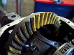
Many of you know that the non sunroof version second row light contains two built in yellow LED's on the circuit board and not an easy swap out. I have completed an LED swap on this light using the third row light as a guide. It is NOT an easy plug and play swap and required some modification to the housing, soldering, and ingenuity. The way I did this was based on the type of bulbs I had and the housing my EX was equipped with. I have a 2013 XLT explorer and this may vary depending on which year you have. Let's begin.
Remove the second row light housing from the roof, it just pops out starting by pulling at the rear of the light. Once it is out take it to your work station. Flip the light so that the circuit board is facing up. There are four tabs that lock into the sides of the housing which hold the circuit board in place. Using a small flat head screw driver gently pry the tabs out of the holes. You may need to work around the board evenly to get it out. Be careful not to crack the board!

Once the tabs are free work the board out of the housing being careful not to bend the connector pins. Lift up and slide the board out.

A few notes about this light. The lights and switches work opposite of each other. In other words when you press the right hand button the left hand LED comes on. The light beams are X'd, meaning they cross. This produces a "spotlight" effect so each passenger can have their light on without disturbing the other.
Let's look at the bulbs I am using. This is a standard 194 bulb and fits almost all the interior bulb sockets. Mine have 5 LED's on them and actually make them quite large for the housing. You may want to look for some smaller ones that will fit better.

I had to remove the white base in order to get these to fit. Bend the leads straight so the base can slide off. My base was "glued" to the light so I had to cut it off with a dremel.

As you can see my bulbs already have a resistor installed to give them the proper load rating. If yours do not have a resistor then follow the instructions further down in this post to add your own.
Now lets have a look at the housing. Mine has two center ports for the LED's, and two push buttons on the left side to operate the lights.

This step is optional but made things a little easier. There are four tabs in the corners of the yellow housing that hold it in. Removing this whole assembly makes it easier to mock up your lights to see how they fit in the housing. Gently pry each tab out of the hole and work your way around to each tab.

Remove the two housings by lifting up on the tabs held by the clips. BE VERY CAREFUL NOT TO BREAK THEM. Pretend you are doing surgery on these next few steps, it's delicate.

Now separate the two halves by unclipping the center snap on the other side.

It's time to test fit your bulbs into the housings. As I said mine are pretty large and a smaller bulb would fit better. The circuit board sits flush with the top of these housings so your bulbs need to sit below the edge of the plastic as to not short out the circuit board. I needed to enlarge the top opening to allow them to fit. I used a dremel to gradually enlarge the area for the bulb. Grind a little and test fit, you don't want to remove more than you have to.

Once your bulb fits bend the leads on the bulb down along the sloping part of the housing. I drilled two small holes in the top edge to allow the leads and bulb to sit a little lower in the housing so it didn't contact the circuit board. I used a small dab of CA glue (or super glue) to hold the bulb in place while I soldered the wires to the bulb. Using some 22 gauge wire that I had laying around solder the wires to your bulb. You don't need much only about an inch and a half. Finish off your solder joint with some heat shrink to prevent shorting.

Do this for both bulbs and make sure everything fits nicely in the housing. Once you have it assembled to your satisfaction snap the two halves back together. If you removed the whole socket assembly then reassemble as shown. Make sure you run your wires through the large notched area to prevent the circuit board from pinching your wires on final assembly.

Now lets turn our attention back to the circuit board. This is where it's the point of no return. You need to shave off the ceramic material and diode off the LED down to the base. I used an x-acto knife to do this. Be very careful not to slip and cut yourself as well as slip and damage any other components on the board. Once you see the silver pads showing up just clean it up. There are two solder pads separated by a little bit of the ceramic, that doesn't need to come off. Just make sure you have all of it off the pads.

The pads will be silver and are hard to see in my pictures but you cannot solder to this. To solder to the pad you need to scrape the silver coating off to reveal the copper under it. My pictures don't show this well because of my camera but you should be able to see what I'm talking about. Once you are down to the copper brush off any shavings and clean up your area. Now you need to tin the pads with solder. Be very easy with the solder, don't glob it on or let it run over and touch the other pad or it will short out.

Now it's time to solder the wires to the circuit board. I'll save you some time and tell you that the larger inner soldering pads on each side are positive and the outer narrower pads are negative. Solder each wire to its perspective side and polarity. Be sure to arrange it so you can flip the housing over and not pinch the wires. Snap the lower light socket assembly onto the main light base making sure you install it correctly oriented so it lines up with the circuit board. Then install the circuit board on top gently pressing the tabs down and into their locking holes. Be sure you don't pinch the wires!


You should now have a fully assembled light housing. Go and test it out to make sure it works and functions properly. While my bulbs were fairly large for this application it functions fine, however I did lose some "spotlight" ability. Each bulb when on pretty much lights up the whole back seat by itself. I don't really mind and if I ever change my mind I'll find new smaller bulbs and change them out.
Third row light solution:
Credit for this goes to chieftomahawk. He did the work and figured it out, I took more pics and will explain in a little more detail.
Remove the housing from the ceiling starting at the front edge. It should just pop out. Disconnect the plug and take it to your work area. On my light the circuit board is exactly the same as my second row light however it seems there is a difference in design from year to year. It shouldn't matter the process should be the same. Gently pry the circuit board out of the housing with a flat head screw driver and pull the circuit board out.

Here it is separated.

Carefully shave the ceramic and diode off the circuit board till you reach the two silver pads underneath. Then scratch off the silver to the copper underneath.

Here is the other version of circuit board.

I had to remove the base of my bulb to make it fit in the housing. Bend your bulb leads to get the bulb to sit where you want it and make sure they exit the housing right by the little prongs.

With your bulb in the housing set it down on top of the circuit board. Remember the larger pad is positive and the narrow pad is negative, did you orient your bulb in the housing correctly? Solder your leads to the board and slide the housing up and over the solder pad.


Flip the board over and reinsert it into the light base. Be sure you line up all the tabs on the bulb housing with the base. This part was a pain to get everything lined up but make sure its lined up before you snap the circuit board fully back in. Once it's in take it out to the car and try it out!
Puddle lights:
For some models, cargo compartment lower side light LED swap:
Pop out housing from side panel carefully with a flat screwdriver.

Pop bulb out of metal holding clips. Replace with LED Festoon type bulb of same size.


Reinsert light housing into panel wire side first.

Vanity mirror light LED swap: COMING SOON
Adding 1K Ohm 1/8 Watt resistors to 194 LED bulbs (if needed, most LED bulbs now come with resistors built in since these original posts):
Original posting on cobaltss.net:
Ok, so you have decided to purchase the 194 LEDs for your car off ebay. Sure, it seems to work fine in the trunk. Works great for the rear plate. Cool, however it does not seem to work well in your map lights inside the car. It seems to stay on all the time, but being super dim. Well I will show you how to fix this problem.
You can do this to any 194 LED light. Here are the ones that I have purchased:

Step One: Go to your local RadioShack store and pick up a pack of 1k Ohm 1/8th Watt Resistors.

Step Two: Take the base of the LED light. Do this by prying the wires from the base. Then pulling the base straight out:

Step Three: Take one of the resistors. Bend one leg at a 90 degree angle. Cut off the leg leaving about 1/8th inch of led. The solder it to one side of the LED light board. It will not matter what side of the resistor to use, since resistors are not polarized.

Step Four: Measure and cut the other led. Then you can bend it towards the other leg. Doing this will prepare the other side. Then solder it.

Last Step: Put the base back on the LED in reverse of how you removed it. Make sure you do this to both LEDs for the map lights. Enjoy normal operation of your map lights.

Yea, I was having the same problems. The cheapo LED's from amazon and JDM ASTAR would last about 3-6 months then start blinking. I then decided to bite the bullet and purchased some from CARiD that ran about $8 a bulb. HOWEVER, I have had them installed both above my plate and on the interior for over a year now and not a single issue.