1997 Ford Explorer - V8 - 5.0 - AWD | Page 4 | Ford Explorer Forums - Serious Explorations

  • Register Today It's free!

1997 Ford Explorer - V8 - 5.0 - AWD

Hello Explorer Fans.

I have been on the forums for some time and have extensively read many threads. I have enjoyed the forums so far. Now I have a question of opinion for you all.

I currently own 97' V6 SOHC Sport and I love it. I was going to SAS it, but Id rather do it to a V8 Explorer, plus, manual TC's are readily available for the swap.

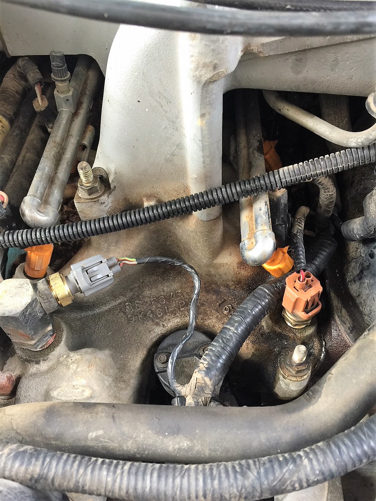
To get to the point, I'm looking at a 97' 5.0 AWD Explorer (166,000 miles) (for a few hundred bucks). It's a solid vehicle, straight but its flashing a few codes. I looked up the codes here on the forums and it appears to be a "simple" fix. It idles well, but has an obvious 'lumpiness' to it. When you accelerate under load, you can sort of hear and feel it. The codes I got were P1132 - Lack of Oxygen Sensor indicates Rich and P1131 - Lack of Heater Oxygen Sensor indicates Lean. Both appear to be O2 sensor issues which may not be that big a deal. The trans seems to shift well with no obvious issues.

I'm very mechanical in nature (I work on my own cars/trucks) and fabrication of all I want to do...is what I do.

I just wanted a few opinions on the success of fixing this issue and any potential things I should look for before i pull the trigger and pick this thing up.

Thanks everyone.


Join the Elite Explorers for $20 each year.
Elite Explorer members see no advertisements, no banner ads, no double underlined links,.
Add an avatar, upload photo attachments, and more!
.


Yeah, whatever you do, don't use a large screwdriver and pry the glass off the (2) glass retainer clips on the upper channel, that's EXACTLY what someone did to my 2000's driver's front window, and I've got to replace the window because of it, because glue it back together? Good luck, I've tried everything, I wish I could though.

That sucks. People have to use better judgement at what their comfortable with doing. When I pulled the regulator out at the junk yard, I used a screw driver and they slipped off very easily. When I tried it on my own vehicle, they were glued on there good. I swapped to trying other methods which led me to drilling out the rivets going forward.


I've got the rivet gun, I just hope it won't break the glass doing those window brackets. I have new glass for almost all of my windows, so it'll be fun.


I've got the rivet gun, I just hope it won't break the glass doing those window brackets. I have new glass for almost all of my windows, so it'll be fun.

Drilling out the old rivets was simple, there were access holes in the door skin that allowed the drill bit to get in there easily.

I used 7/16 x1/4x1/2 bolts and nuts and thread locker (or lock washer), worked like a charm. Reaching your hand behind to mount the regulator to the inner skin was an easy task.


Probably a stupid question but busting the glass? There holes in the bottom of the glass? I hate working on car doors so this is all new to me since I don't make a habit of them.


That is a great question, how much is tight but not too tight?


Probably a stupid question but busting the glass? There holes in the bottom of the glass? I hate working on car doors so this is all new to me since I don't make a habit of them.

No holes in the glass. There are 2 'clamp' brackets that are epoxied to the bottom of the glass. Those brackets attach to the regulator arm that moves up and down.

The bolts I used I made hand tight since they don't pivot or need to move - Just hold the glass to the regulator. Their tightness have no bearing on the glass itself.
That's right, I forgot that. The old Fords(70's etc) have holes in the glass which have brackets riveted on with. The newer method is much better, just sealant well sandwiched in a bracket.


Keeping the rear channel lubricated with silicone foam spray is the key to prevent it from "window clocking" again. The rear edge of the window gets snagged but the regulator keeps pulling it down, and after several times the glue clamp lets go. The front channel needs some lube also but the rear being a longer guide is the hang up.


I have had success using layers of 2 sided tape in the channel part,use a metal straight edge to get it into the channel good, leaving the backer strip on the exposed side. Use a c clamp to adjust (bend) the bracket to just the thickness of the glass.
Now, shove the glass in and then remove the backer from the tape to the glass, which is the tricky step. Then bolt the brackets to the regulator.


Just wanted to drop a quick update. The Heater Fan issue has been driving me CRAZY.

I went to the JY over the weekend to pull a 'new' fan just to make sure the fan that have wasn't the culprit. I replaced the fan motor resistor assembly before and no change.

To reiterate my issue - Fan blows at all speeds but, the air just didn't seem to be flowing appropriately though the vents. Heck, I even thought the fan was blowing backwards.....So I compared it to my 97 Sport. (nice to have a 2nd working vehicle to compare) When I turned on the fan in the V8, it sounded louder as if it was working harder than normal. TORNADO!

I pulled the 'old' fan and installed the new. Turned it on and no change (Argh!)....so I just sat there (frustrated :shoot:) thinking of each aspect of the system to ensure I didn't overlook anything...Im telling you, i checked everything next to pulling the box and cutting it open!....Then it hit me - the only thing it HAS TO BE is maybe a rodent built a nest in the box (remember I pulled a ton of acorns from the fan area when I got it)...there wasn't anything flying out of the vents...but hey, what the heck....its got to be the only reason why air was not moving in the box.

As the fan was on full blast, I went under the hood to feel around the fan and box area on passenger side....I notice that air was blowing on the outside...it was coming from the rubber cooling hose that connects the fan motor to the box...Air WAS moving! Comparing to the other Explorer, it wasn't right. It was like a compressor blowing air from an open hose....

So I pulled the fan back out to look inside...I noticed on the Evaporator side there was a pocket but it had what looked to be factory insulation in the hole....NO...it was a dang squirrels nest that was blown/compressed up against the fins....I swear, it was so perfect that it looked 'factory' in nature. I got the shop vac out and sucked all that I could...I figured, if it was 'factory', Ill just throw some jute I had with my upholstery gear to replace it....

Are you kidding me! That was it!

Now the fan sounds 'smoother' and quieter just like its little SPORT brother.

A definite 'hammer on the head' moment for me; but hey, I'm still happy none the less....and one less Gremlin to worry about! :bounce:

I hope this helps someone....

.


Good deal, done. Did you find the white striped gremlin in there, Spike was his name?


Worked on the Ex again this weekend to attempt to fix the 'non-working' Temp gauge. Having experience with this sort of thing, I pulled the wire and grounded the lead and the gauge maxed out as it should.

I checked ohm's on the temp sender and I was not getting anything on the meter. So I picked up a new one and installed it...nothing...not even any resistance on the single pin output for the gauge.

I re-installed the old unit and checked resistance on the single pin (used by connector) again, still nothing. So, I swapped over to the other un-used pin, and got roughly 2.3 milliohms on the meter. That seemed very odd to say the least since nothing (no factory wire) connected to that pin. I checked resistance between the pins and got nothing as well. So I assumed the sender I got was bad and returned it for another - different brand.

Got home, installed it.....The same thing. No reading...except, i did notice the gauge needle moved 'colder' (below cold) and did not move to indicate any heat in the block. I turned the heater on to ensure the water was heating...Yes, there was heat, but no movement on gauge needle. I re verified the gauge again, by grounding it...still functions as it should.

(see fix below)

I know there is a 2nd temp sending unit for the PCM (??) on the left. (see picture below) It has 2 wires on it. So, I thought maybe the temp sending unit issue might be with it. I swapped the new sender into it and made the connection....still nothing.

index.php

TempSendingUnits.jpg


Notice the connector differences on the senders - My question is, are these 2 senders different in functionality because they feed 2 different sources and/or do these work in conjunction to make the gauge function properly....I'm stumped...Im assuming the wire to the gauge has to be good since it responded to the ground I applied.

(Now, I did not pick up a 2nd sender to ensure 2 new units were installed. Since I did not get any changes, I held off to see what you guys thought) The new 'Generic' sender I got from Oreilly's did not have the 'tang' or slot on the top side of the connector, so it 'interchanged' between the two connection points easily.

index.php


****This factory one below goes to the left (PCM) has the slot in the middle (left side of connector)

index.php

TempSendingUnitPCM.jpg


This is a close up of the sender the gauge connects to - Notice the slot is located off center to the right.

index.php


Fix: I had this same problem on my 1999 Mercury Mountaineer. Same engine and electronics to dash. Both had bad thermostats. There is a picture of the bad thermostat in the 1997. Once I got the engine warmed up again after all the repairs, the temp gauge started working as it should.
TempSendingUnitGage.jpg


One works the PCM, one works the needle, if memory serves gray is for the PCM and the burgundy or orange one depending on who you ask is for the gauge.


Thank you.

Is there a 'specific' sender required for the gauge and PCM? Ground testing confirms my gauge to be working, but new senders are not sending the right signal to gauge to work correctly...plus I'm not getting resistance on the sender when I test across pins.

I'm going to stop at the JY this week and pull a couple from cars to install and test/play around with.


I believe they're identical but the connectors won't swap, if memory serves, I'd just stop at the JY anyhow, I gave $1 a piece for the last ones I bought, they work just as good as a new one and I saved $20 a piece.


Alright! I went to the JY on my lunch break and picked up 2 senders - Ill keep you posted on what I find out.


I installed the 'new' units and ....NOTHING! I cant imagine both were bad. I did a resistance check on them after it warmed up. I was seeing 2.85k ohms on the meter (set at 20k ohms). The gauge still registers to hot when grounded.... Either the sending unit is not grounding properly or .... hmmm. My next check to to verify the wire from the sender has continuity back to the gauge cluster....I'm betting its good.

Does anyone know if the gauge is 'swappable' like the older style or is it integrated in the cluster as one piece on the circuit board?

Anyone else want to chime in? @CDW6212R ??? I have read multiple threads and they swing from replacing the thermostat (not sure how this would do anything) to replacing both sensors. I'm not sure or clear on the fact that the PCM sensor has any affect on the gauge operation itself.

I'm not opposed to putting in an aftermarket gauge - I planned on fabricating a pillar gauge/switch holder in the future anyways.

Thanks!


I'd suspect the gauge itself too. It seems that you've checked just about everything else.

The gauges are pressed into place in three pieces in these clusters. The middle section is the speedo/tach, and the two side parts are for those pairs of gauges. The faces differ in various models, but I think any 2nd gen temp gauge will swap directly into your cluster.

You just remove the cluster, then the several screws around the edges, take the cover off, and gently pull the gauge sections out. They all have steel pins, sharp and pointed, which engage into small holes in the cluster housing. The three sets overlap slightly, I forget which has to come out first. It's very easy to figure out and do. The only thing to watch for is to not touch the fragile gauge needles.


Join the Elite Explorers for $20 each year.
Elite Explorer members see no advertisements, no banner ads, no double underlined links,.
Add an avatar, upload photo attachments, and more!
.


Just a stupid question, but, have you checked all fuses? there are at least 3 protecting the cluster IIRC.

Not a stupid question - I was not aware of this. Thanks!


Back
Top