2003 Centennial 4.6L Engine Removal | Ford Explorer Forums - Serious Explorations

  • Register Today It's free!

2003 Centennial 4.6L Engine Removal

2000StreetRod

Moderator Emeritus
Joined
May 26, 2009
Messages
10,597
Reaction score
334
City, State
Greenville, SC
Year, Model & Trim Level
00 Sport FI, 03 Ltd V8
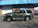
Unfortunately, I purchased a 1 ton crane for removing and installing the 4.0L SOHC V6 in my 2000 Explorer Sport. At the fully extended boom position the boom was too short to reach the engine center of gravity. I ended up having to remove the front bumper to get the boom chain where it needed to be. Surprising to me, I may not have to remove the bumper on my 2003 Centennial (Ford's 100th anniversary Explorer Limited). The photo below shows the boom assembled according to the instructions. I recently purchased a load leveler for better control when working alone.
BoomStock.jpg

Routing the chain out of the front of the boom instead of the bottom extends the reach about 2 3/4 inches. Almost enough to reach the engine center of gravity.
BoomMidEng.jpg

I can gain another half inch of reach by removing the front license plate mount.
TagMount.jpg

The higher the lift, the shorter the reach. Folding the chain within the boom reduced the lift about 7 inches.
BoomMod.jpg

Since it may take a long time to remove the stock engine and install a 4.6L DOHC I added fuel stabilizer to the fuel tank and took a couple short drives to make sure it was well mixed.


Join the Elite Explorers for $20 each year.
Elite Explorer members see no advertisements, no banner ads, no double underlined links,.
Add an avatar, upload photo attachments, and more!
.


I have a 2002 Explorer shop manual CD and a 2003 Explorer shop manual book. Both contain engine removal procedures that involve removing the transmission and purging and removing most of the A/C system. From posts on the forum I know that this is unnecessary but I could not find an appropriate detailed engine removal process. I know from removing and installing my Sport engine that a detailed removal procedure is very helpful during engine installation. The removal steps are accomplished in reverse order. Therefore, this thread will document my rear wheel drive engine removal process for my benefit and possibly other forum members.

1. Block rear wheels & set parking brake.

2. Unlock doors & rear hatch.

3. Roll down windows if in garage. I put down the rear seats & covered the area from the back of the front seats to the rear hatch for storage of removed parts.

4. Place transmission selector to Neutral. I may need to roll the Explorer partially out of the garage when actually removing the engine with the crane.

5. Remove engine appearance cover.
EngAppear.jpg


6. Disconnect battery terminals & insulate battery posts.
BatryTerms.jpg


7. Disconnect windshield washer hose from hood. I chose to cut the hose since retainers were brittle & likely to break when attempting release. I will splice after DOHC engine installed.
WashHoseCut.jpg


8. Mark hood location relative to hinge on both sides.
HoodMark.jpg


9. Support hood in open position. I used my crane.
HoodSupport.jpg


10. Protect fenders & cowl.
FendersProtect.jpg


11. Remove hood bolts.

12. With a helper (I used the crane) remove hood & set aside.
HoodHelper.jpg

The hood is light weight and easily maneuvered by one person once removed from the vehicle.


13. Loosen clamps at each end of air cleaner outlet tube (red arrows below).

14. Detach speed control cable from air cleaner outlet tube (yellow arrow below).

15. Separate outlet tube from MAF sensor.
IntakeTube.jpg

16. Disconnect resonator tube from air cleaner outlet tube (blue arrow above).

17. Disconnect crankcase vent tube from air cleaner outlet tube (green arrow above).

18. Disconnect outlet tube from throttle body & set air cleaner outlet tube aside.


19. Spray exhaust downpipes to manifolds retaining nuts & studs with rust solvent (PB Blaster).
DownpipeD.jpg

I was unable to access the inboard passenger side nut & stud from under the vehicle. I'll have to wait until I remove the passenger side wheel & splash shield to gain access.

20. Remove the accelerator return spring.
ThrottleSpring.jpg


21. Disconnect the accelerator and speed control cables from the throttle lever.
ThrottleCables.jpg


22. Detach the accelerator and speed control cables from the bracket.
ThrtlCblRetainers.jpg

I broke one of the brittle tabs on the throttle cable retainer. I'll use a small hose clamp as a retainer in the future.

23. Detach the accelerator and speed control cables from the retainers, and position the cables aside.

24. Disconnect brake booster hose at the intake manifold (red arrow below).
BoosterNPurgeHoses.jpg

25. Disconnect fuel vapor purge valve vacuum hoses at intake manifold (yellow arrows above & below).
VapPurge3.jpg


26. Disconnect fuel vapor purge valve electrical connector (red arrow below).
VapPurge1.jpg

27. Remove fuel vapor purge valve retaining nuts & bolts (yellow arrows above & below).
VapPurge2.jpg


28. Secure fuel vapor purge valve & hoses out of the way.
HosesAside.jpg


Watching.


29. Open pressure relief cap on degas bottle.

30. Place a container under radiator draincock (bottom of radiator on passenger side) and drain coolant.
DrainCock.jpg


31. Close draincock.

32. Remove the upper air deflector by prying upward under the driver side & then pulling toward the driver side.
UpAirDeflect.jpg


UpAirDeflect2.jpg


33. Remove degas bottle upper hose clamps.

34. Disconnect degas bottle upper hose at radiator & position aside.

35. Remove radiator upper hose clamps.
UpRadHose.jpg


UpRadHose2.jpg


36. Remove radiator upper hose.

37. Disconnect A/C pressure switch connector & detach the A/C tube from the retainers.
ACPresSwitch.jpg


ACTubeClamps.jpg


38. Remove the 2 screws (red arrows) & 2 bolts (yellow arrows) from the radiator fan upper shroud.
RadUpShroudD.jpg

Driver side above & passenger side below.
RadUpShroudP.jpg


39. Remove the radiator fan upper shroud (red arrows below) by pulling the driver side upward first then the passenger side.
RadUpShroud.jpg

40. Remove the inner air deflector (yellow arrows above) by just lifting it up.

40. Protect the radiator with cardboard.
RadCardBoard.jpg

Mine has paint over spray on it so doesn't show up well in the photo.

I purchased a fan clutch wrench set for my Sport & it works on my Centennial.
FanClutchWrench.jpg


41. Remove the cooling fan blade & clutch assembly.
FanClutchRmov.jpg

The large nut loosens counter-clockwise when standing in front & facing aft.

42. Disconnect the lower air dam pushpins & lower air dam by prying away the 4 push pins.
LwrAirDam.jpg

My hand held weed removal tool works well as a pry bar on push pins.


43. Position coolant catch pan & remove degas bottle lower hose clamp at radiator.
LwrDegasClamp.jpg


44. Disconnect degas bottle lower hose at the radiator.
LwrDegasHose.jpg


45. Remove degas bottle lower hose clamp at degas bottle.
LwrDegasHose2.jpg


46. Remove the radiator lower hose clamp.
LwrRadHose.jpg

47. Disconnect radiator lower hose at radiator.

48. Remove the radiator lower shroud bolts.
LwrShroudBlts.jpg


49. Detach power steering hose retainer from shroud.
PSHosRetain.jpg


50. Detach degas bottle hose retainer from shroud.
DegasHosRetain.jpg


51. Remove shroud by lifting upward.

52. Remove degas bottle lower hose.


I could not break loose the hose at the degas bottle so I decided to remove the air cleaner box/ MAF sensor by lifting to release the bottom and then pulling toward the driver side.
AirFltrEnclsr.jpg


Then I removed the degas bottle with the lower hose attached after removing the 3 mounting bolts.
DegasBtlRmvd.jpg


This will provide better access to the front & rear heater flow control manifold which may have to be modified for the DOHC V8 installation.

53. Remove the safety retainers from the oil cooler quick coupler connectors.
OIlCoolerCnx1.jpg


54. Use the special tool to disconnect the quick couplers.
OilCnxTool.jpg

I have three different metal 3/8 inch dia. disconnect tools but none are stepped to fit over the ridge on the Ford 5R55W oil cooler lines. I dislike plastic tools so I ordered a Lisle 39660 since I couldn't find one locally.
Lisle39660.jpg

It should arrive next week. I have one just like it but isn't stepped.

55. Disconnect the cooler oil lines support bracket from the studbolt.
TOilLinesBrkt.jpg


... removing and installing the 4.0L SOHC V6 in my 2000 Explorer Sport... I ended up having to remove the front bumper to get the boom chain where it needed to be. Surprising to me, I may not have to remove the bumper on my 2003 Centennial (Ford's 100th anniversary Explorer Limited).
When I hooked my 4.0 V6 out of my 2002 (same body as yours), I had to pull off the bumper cover and the crash bar behind it, as well as the headlights and the headlight support, in order to get the crane hoist close enough to the CoG to safely pick it up.The only tips I'd offer are to set your chain as short as possible, and remove the intake so you can get your leveler as low as possible to the block. My hoist barely got the engine high enough to clear the top of the radiator support.

I also found it helpful to remove the radiator.

Good luck, and keep up the documentation!


I had to suspend work on the engine removal for a few days to do some yard work. I was afraid I might be attacked by a neighbor as Senator Rand Paul was for not keeping up with leaf removal.

56. Remove the 2 bolts in radiator right support bracket & remove bracket.
RadBrktP.jpg


57. Remove the 2 bolts in radiator left support bracket & remove bracket.
RadBrktD.jpg


58. Support both sides of the A/C condenser right side with wire.
CondWireP.jpg


CondWireD.jpg

59. Remove the A/C condenser support bracket bolts (red arrows above & below) & remove brackets.
CondWireP2.jpg


ACBrktP.jpg


ACBrktD.jpg


60. Separate the push pins from the radiator lower air deflector.
LAirDamPins2.jpg


61. Lift the radiator up and off the mounts & set it aft with the radiator frame mount tabs resting on the vehicle frame.
RadAft1.jpg


62. Remove the left inner air deflector from the A/C condenser by pushing it outboard.
AirDeflectD.jpg


63. Remove the right inner air deflector from the A/C condenser by pushing it outboard.
AirDeflectP.jpg


64. Lift the A/C condenser up off the lower support. Move the A/C condenser toward the front of the vehicle. I was able to lift the A/C condenser off its mount but not forward at the top.
ACFwd1.jpg


65. Remove the radiator & trans cooler as an assembly. (I was unable to do so since the cooler hoses were not disconnected.)


The oil cooler line disconnect tool arrived and I tried to use it today. Even though it fit correctly and I oiled the connectors I was unable to release either connector. I even tried tapping the side of the tool to make sure it was completely seated in the fitting. So I tried another approach. I removed the bolts that attach the cooler to the radiator.
OilCoolerBoltP.jpg


OilCoolerBoltD.jpg


Then I pulled upward on the cooler and separated it from the radiator providing limited access to the hose clamps.
OIlCoolerCnx2.jpg

The hose clamps are a metal band with prongs on one end and matching holes on the other end. To install them the band is wrapped around the hose and then the holes are pressed against the pins to engage them. Then a portion of the band is crimped to make it tight. There isn't enough room to cut the crimp off with diagonal cutters but I was able to rotate the band in position to pry the end away from its mating prongs and then pull the entire clamp off grasping the end with locking pliers. Then I pried the hose off the fitting.
OIlCoolerCnx3.jpg

The lower clamp is even less accessible but after much twisting, prying and pulling I was able to beak it loose and lifted the oil cooler up and out without damaging it or the radiator.
OilCoolerOut.jpg


My 2002 and 2003 shop manuals both state that to remove the oil cooler/radiator assembly it is not necessary to disconnect any A/C lines or hoses. I'm beginning to doubt that. The radiator frame mounting tab interferes with a large, almost rigid A/C line on the passenger side.
RadTabACP.jpg

The other tab on the driver side interferes with the condenser line.
RadTabACD.jpg


I'll probably set the radiator frame back on its mounts and disassemble the radiator from the radiator frame.


I'm proceeding with my plan to separate the radiator core from the radiator frame while in the vehicle. I set the radiator assembly back in its mount on the driver side so it couldn't fall on me while I was under the vehicle. Then I removed the pushpins that attach the lower splash guard to the radiator.
RadGuardPins.jpg


I separated the splash guard aft section from the radiator core and then pried down and loose the forward section.
RadGuardDown1.jpg


RadGuardDown2.jpg


That allowed me to separate the degas bottle supply hose from the radiator.
AirGasBtlSupHose.jpg


There are 6 bolts that attach the front of the radiator core to the radiator frame. 2 were already removed when I separated the oil cooler from the radiator. I removed the lower 2 bolts and then found a "helper" to hold the core until I remove the upper 2 bolts.
RadCoreHold.jpg

I threaded on hand grapevine trellis wire thru a pair of holes in the top of the radiator near each side to attach the load leveler. I secured the A/C tube aft of the radiator.
ACTubeSecure.jpg


Then I removed the upper 2 radiator frame to core bolts and carefully raised the crane boom making sure the core remained free.
RadOut.jpg


Once the core was removed it was very easy to remove the radiator frame right side bracket with the splash shield still attached via the degas tube clamp and the left side bracket.


The battery cables are part of a wiring harness that connects to the BJB, alternator, starter motor & solenoid, oil pressure switch, A/C clutch & the body. I decided to follow the shop procedure to leave the wiring harness connected to the engine even though eventually I will separate the two and modify the harness to install on the DOHC engine.

69. Disconnect the battery ground terminal.
BatGnd.jpg


70. Open BJB cover & disconnect the positive battery supply & alternator charge terminals.
BJBTerminals.jpg


71. Disconnect the ground strap by removing retaining bolt.
GndStrap.jpg


72. Disconnect C139 12 pin connector with only 5 pins used.
C139.jpg


73. Separate battery wiring harness from battery tray & position harness above engine.
BatNTray.jpg


BatHarnPosn.jpg


On the Ford modular V8s the starter motor mounts to the transmission bellhousing.
BellHousingStrtr.jpg

The torque converter nuts can be removed via the removed torque converter access opening. Surprisingly, the starter opening is not large enough to install a socket on the flexplate retaining nuts.
StarterRmvd.jpg


I noticed while under the vehicle that the wiring harness that connects to the starter and A/C compressor clutch is routed below the transmission cooler lines instead of above. That would be a problem when lifting the engine without first removing the cooler lines.

The starter solenoid terminals and 2 of the starter retaining bolts can be accessed from under the center of the vehicle. However, I was unable to access the top starter retaining bolt from that position. Removing the right front wheel & aft fender splash shield provides better (though still difficult) access to the bolt.

74. Remove starter motor solenoid terminals cover.
StartSolCvr.jpg


75. Disconnect solenoid to battery terminal (red arrow below).
StartSolTerms.jpg

76. Disconnect solenoid to battery junction box terminal (yellow arrow above) & position harness aside.
StartSolTerms2.jpg


The shop manual shows 2 bolts and a studbolt attaching the starter but there were 3 bolts on mine. Possibly on earlier models there was a ground wire that attached to the studbolt.
StarterBolts.jpg

77. Loosen the bolts in the order numbered above to reduce the tension on bolt 3 which is the hardest to access.

78. Remove bolt 3. This is a difficult and tedious task due to the limited access. Removing the right front wheel and aft splash shield improves access to the bolt as well as to the exhaust downpipe to manifold retaining bolt. I was successful using a 1/4 inch drive with a short extension & 13 mm socket.
StarterDrive.jpg

The exhaust manifold heat shield limits the rotation of the socket handle.

79. Remove bolt 2.

80. Support the starter while removing bolt 1 & then lower the starter out of the vehicle.

Here's a link to a video about removing the starter:


Note: The following unnumbered steps associated with removing the battery wiring harness are not necessary to remove the engine. If the wiring harness is to be transferred to another engine, it would be much easier to perform the task when the engine is on a stand.

I was able to access starter retaining bolts 1 & 2 but the wiring harness was in the way when trying to access bolt 3 so I detached the harness support bolt from the motor mount.
StartHarnBrkt.jpg


I also pried loose the harness support cap at the A/C compressor bolt.
ACHarnSprt.jpg


I disconnected the A/C compressor clutch connecter (red arrow below).
ACClutchCnx.jpg

I separated the wire retainer to free the wire and connector (yellow arrow above).

Then I was able to position the harness far away from the starter.
BatHarnAC.jpg


I continued separating the battery wiring harness from the engine by disconnecting the oil pressure switch connector.
OilPresSwitch.jpg


I separated the power steering fluid return hose from its clamp.
PSRetHosClamp.jpg


I removed the nut from the power steering fluid return hose/wiring harness bracket stud and the nut that attaches the bracket to the front cover
PSHarnessBrkt.jpg


I disconnected the alternator connectors (red arrows below).
AltCnx.jpg

I pried loose the wiring harness retainer from the valve cover stud/bolt (yellow arrow above) and the fuel rail post (black arrow above).

I removed the left front fender forward splash shield by prying loose the push pins. That gave me access to the power steering pump stud/bolt nuts that retain the wiring harness positioning bracket.
PSPumpBlts.jpg

Then I separated the ground wire terminal & wiring harness support from the stud/bolts.

Then I detached the wiring harness from the valve cover stud/bolt.
BatHarnVC.jpg


Finally, I carefully worked the battery wiring harness up and away from the engine. It was difficult because the metal support straps were still clamped around the harness.

Note: The above unnumbered steps associated with removing the battery wiring harness are not necessary to remove the engine. If the wiring harness is to be transferred to another engine, it would be much easier to perform the task when the engine is on a stand.


Join the Elite Explorers for $20 each year.
Elite Explorer members see no advertisements, no banner ads, no double underlined links,.
Add an avatar, upload photo attachments, and more!
.


81. Remove the 2 bolts retaining the inspection plate from the transmission.
TransInspect.jpg


The plate drops when the 1st bolt is removed & the 2nd bolt is loosened.
TransInspect2.jpg


82. Remove the torque converter access plug.
TCPlug.jpg


83. Using a large drive & 18 mm socket on the harmonic balancer rotate the flexplate until a torque converter stud/flexplate retaining nut is accessible.
TCNut.jpg


My flexplate has a 4 bolt pattern and I probably have an 8 bolt torque converter with an adapter between the flexplate and torque converter.
TCAssy.jpg


84. Using a 15 mm deep well socket (making sure it is seated on the nut) and a large drive remove the first nut.
TCNutSkt.jpg

I use 6 point sockets to reduce the chance of rounding the nut corners. The 1/2 inch drive and 3/8 inch drive shown below worked for me. I loosened the nut with the large drive then removed the nut with the small drive.
TCSktDrives.jpg

The torque specification for the nut is 28 lb-ft but it took at least 50 lb-ft to loosen the nut. I had to use a "cheater pipe" because I pressed the socket against the nut with my left hand while rotating the drive handle with only my right hand. The nuts appear to be locknuts.

85. Rotate the flexplate 90 degrees & remove torque converter stud/flexplate retaining nut until all 4 have been removed. The 4th nut was a problem because I needed 3 arms; 1 to push the socket against the nut, 1 to rotate the socket drive, and 1 to keep the crankshaft from rotating. I tied my torque wrench to the frame to keep the harmonic balancer retaining bolt from turning.
CrankHldr.jpg


Back
Top