Digital Dash Swap? | Page 14 | Ford Explorer Forums - Serious Explorations

  • Register Today It's free!

Digital Dash Swap?

ok think i know what it is. Im using a 12v 4.5 amp battery, and it just doesn't have enough to power the light bar. Have to figure somethinguelse out. Good news is i was able to test my explorer spec message center and it powers up and seems to function correctly.
Posted via Mobile Device


Join the Elite Explorers for $20 each year.
Elite Explorer members see no advertisements, no banner ads, no double underlined links,.
Add an avatar, upload photo attachments, and more!
.


geoph did you ever get an answer from the turbo bird forum about the oil pressure resistor?
Posted via Mobile Device

FYI, the T-bird/Cougar oil pressure mod is the same as the Explorer, swap the oil switch for a "real" sender and bypass the 20 ohm resistor on the back of the cluster. So,I posted this question on TCCOA.com, in the "how to convert your oil pressure gauge" thread (http://forums.tccoa.com/showthread.php?t=75977).

"How would this work with a digital cluster on an '89 Cougar LS? Is the resistor by the oil sender or is it part of the cluster circuit board?"

This is the response I got.

Probably not(but I'm guessing). The 20 ohm resistor just acts to position the pointer (which is a voltmeter or ammeter) into the normal range on mechanical gauge.

There are two possibilities(and tips to experiment):

1)If there is a true analog to digital converter in the cluster(like the temp gauge), you can connect a variable resistor with say 0 -100+ ohms and see if the bars change. This experiment will determine if there is an analog to dig converter. Or just buy the oil sender and see if it works. You may have to place another resistor in series or parallel to get it to work thru the range (like biasing).

2)If it is just wired to light up 1/2 the bars if the on/off switch registers oil pressure(eg 14 volts), then you have to do some engineering and get a hold of a VU-level meter type integrated circuit which can light up the segments as the voltage changes. I wanted to do something like that for the auto 4x4 on my explorer, as the coil energizes and locks the clutch in the xfer case, I would have a bar graph showing engagement.

That assumes you can control each segment individually (there is no multiplexing on the display).

I believe these cars have the 20 ohm in the wiring harness by the oil sender, not sure about the digital ones though.


Basically the answer is "I don't know". So I then started a new thread, telling of the digital cluster swap, hoping to get a better response.

"Hello all,
This is my first post. I became a member to this forum, because I saw the blue tint mod for the early Cougar digital instrument cluster. In fact I liked the cluster so much I have decided to try to install one into my '94 Explorer ,and have 2 other guys trying this at the same time). I've done the research and all the gauges will work without a problem. But I do have a question about the oil pressure one.

Just like the Explorer, the Cougar uses a dummy gauge for oil pressure, and I would like to have real oil pressure on the digi-cluster. I know that on the Explorer the 20 ohm resistor is on the rear of the instrument cluster, as it is on some of the Cougars. I also know that the resistor moved to the engine compartment in '90 or '91. All references I have found regarding the resistor for the Cougar's cluster are for analog gauges. Where would the resistor have been on the donor car I got this cluster from. The donor was an '89 Cougar LS, and the date stamp on the cluster itself is February 13, 1989. Any help with this would be great.

Thanks in advance.

P.S. I have a thread on this at Explorerforum.com. Search "digital dash swap".


And this is the response I got.

"You posted this in the oil pressure gauge mod thread, and I gave my opinion, check there. I believe the resistor should be in the wiring harness near the sender. You can always check things out with a ohmmeter."

how did yall test the stock light bar? I cant seem to get mine to light up using the cougar cluster plugs for bench testing...

I tested the light bar on it's own by connecting power & ground to the outer pins by means of a 12v house alarm battery. None of the bulbs in the blue sockets lit up. I then swapped in the grey based bulbs (like arco) and it lit up fine. I read somewhere that those blue based bulbs are halogen.

I haven't made any progress...My foot gets sore unless it's elevated, and the prescribed pills are potent. I'm still not satisfied with the way I have the displays mounted. The display sandwich is a bit on the thick side, so I'm trying something as an alternative...and see if it works better. If not I will stick with the way they are mounted now.


Hi there, this is an awesome thread. I'm the guy over at TRS who did the Taurus Digital Cluster. I was going to pull it out and do some refinements (don't have a 4x4 so I was going to move the highbeams/parking brake to the 4x4 dummy light section, among other mods), but after seeing this I may be doing something substantially different! :thumbsup:

One thought on the LED backlighting. Before I did the Taurus Cluster I did the LED swap in my gauges. I bought several different varieties of LEDs and tested them out to see what would give the cleanest output. I ended up with these:

wled-whp6.jpg


They have no upward facing LED, so the light you get coming up at you is what is reflected off of the back/side surfaces. I also lined the back of the cluster with aluminum duct tape (the kind that is super-reflective), which gave me extremely even lighting (the hotspot with the 45 looks worse on camera than it ever did in real life):

img_1946.jpg


If I can find a cluster locally, I'll probably give this a whirl and I'll probably use those bulbs. I also used them in my Accord and had the same success.


ah, very clever! You know we are all goin to pick your brain with questions. First of all, how accurate is your message center to real life? What about distance km empty and all that good stuff. How did you wire in the taurus cluster and how did you mount it. :)
Posted via Mobile Device


Where did you get those?

SuperBrightLEDs.com

NICE59FORDF100 said:
ah, very clever! You know we are all goin to pick your brain with questions. First of all, how accurate is your message center to real life? What about distance km empty and all that good stuff. How did you wire in the taurus cluster and how did you mount it. :)

Actually, I'd love questions. I never did a proper documentation of how I did everything so questions are about the only way I have of sharing it all.

How accurate is the message center? Very. The Taurus and Expo MCs are within .1 mpg of each other. In terms of real world, it's within 3-5% (around 1 mpg). Although the materials I've read indicate that the fuel flow signal is supposed to be corrected for engine size at the computer and NOT the MC, my fuel used on the Expo MC is consistently .8-1.0 gallon *lower* than real life. The Taurus Tach is off and I believe it's due to it expecting a 6 cyl and I only have a 4 banger (the Taurus clusters only came on the 3.8 Taurus/Sables). That said, the fuel level and distance to empty generally are pretty spot on. I keep the Expo MC on average MPG and the Taurus on Instantaneous MPG, and even if they're off, the numbers still give me an idea of how I'm doing.

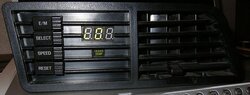
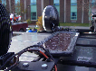
I mounted the Taurus cluster the same way everyone has proposed mounting the Mercury clusters: taking an old Ranger/Explorer cluster, hollowing it out, and fitting in the components. The Taurus cluster was a little difficult because it's one solid PCB that just barely fits in the width of the regular housing. I very quickly stuck in some tinting film to hide the circuit board, but since some of the wires come up (towards the plexiglass) it distorts the film, as you can see in the photos on the upper left. I'm going to unsolder the leads from facing forward and reroute them backwards to eliminate that problem. Also, the cluster is just held on with some zip ties, which is another thing I was planning on fixing this winter.

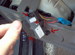
To wire it in I went to great lengths to keep the stock Ranger wiring in place. I took the flexible PCB from the Taurus cluster, cut out the "plug" on the cluster housing and stuck the Taurus plug into. Then I took the wires and hooked them up to the stock Ranger flexible PCB so I could continue to use the stock wiring harness. I had to run four extra lines (Buttons 1, Buttons 2, Fuel Flow, and 12V Battery) which I used a computer Molex (5.25 drive) connector to do so. I ran the fuel flow wire through a firewall grommet where I had already run wiring for the temp sender for the Overhead Console I swapped in. The Taurus temp sender (really just another ECU Coolant Temp sensor) takes two wires, but one of them just goes to ground so I reused the original signal for that.

My winter project is to remount the Taurus cluster, redo the wiring for the extra wires, reroute the High Beams/Parking Brake lights to the 4x4 indicator lights (actually have the parking brake there now, the high beam appears to always be live and the stalk interrupts the circuit, turning on the light. So just changing the pins causes the light to always be on until switch to high beams, which then turns it off... so to do things I'm going to have to completely rewire one of the lights to the High Beams circuit. I'm also tearing out my dash (I'm going to swap in Power Locks/Mirrors/Windows and Fog Lights) so I'm going to make the fuel flow/OHC temperature come through the stock wiring harness and make it all look pretty. Lastly, I'm going to take the VSS, hook it up to the cluster on the bench, and advance the odometer to the correct number. Lots of little details.


awesome thank you for explaining some of those things. You did what i was planning on doing and that was installing basically two message centers in one vehicle. I was also goin to do the same thing, keep one really for average or any other system vital, and use the one in the cluster for instant mpg. I got used to the one in the town car i recenty drove for 11 months, i have to have one lol. I still think im just goin to splice into tin stock explorer plugs in the dash and have the cougar plug perm. installed it the truck. Cause i know i mod like this one, im probably goin to be pulling is out more than once, :) and unless i find a better way, im goin to have to go the same route on changing the odometer. Ive got to add over one hundred thousand miles to have it be correct. Anyone know of a speedometer place near them they could ask?
Posted via Mobile Device


locovaca,
It's great to have you part of this thread. You mentioned connecting the VSS on the bench to correct mileage. Do you know if this would work in reverse, if the cluster displays higher mileage than the truck actually has?


locovaca,
It's great to have you part of this thread. You mentioned connecting the VSS on the bench to correct mileage. Do you know if this would work in reverse, if the cluster displays higher mileage than the truck actually has?

Reverse definitely is not possible without some sort of flashing. In fact, my cluster actually increases the odometer reading when driving in reverse... maybe analog clusters also do that but I didn't think they did.

When I did the Taurus cluster I didn't connect the two data lines from the computer because they're not necessary for the operation, but I'm guessing these are the lines that are used for programming the odometer. On the Taurus cluster then run into the control unit for the main speedo/odometer which furthers my belief in that. Unless you have some sort of EEPROM reader (and would be willing to desolder the appropriate chip as I don't think it was removable otherwise), you are probably looking at a Ford dealer to flash. And I'd be surprise if you could find one with the equipment to do so, with digital clusters being rare beasts anyway.

I don't exactly know the applicable laws and stuff, but I'd think you'd be ok with a gauge having a higher odometer reading than reality than the other way around.

I did some rough calculations on adding the miles. At 8000 ppm, you would have to get the VSS going at 8000 rpm to simulate 60 mph. For 14k miles for me, that means about 233 hours, or under 10 days of constant running. If you can get it up to 100 mph it only takes just under 6 days (not sure what the limit on the gauge is but I wouldn't think it's much over 100), and that's spinning the VSS at 13.3k RPM. Taking it up 100k miles would be quite the daunting task.


ok. I found out what the speed button does. Helps if you read the owners manual :) when above 20 mph, you can hit the speed button at a desired speed and that sets a speed alarm. If you go over that set speed by 5 mph, a tone will be generated and the 'Speed Alarm' icon will illuminate to the right of the speedometer, below the MPH symbol. It doesnt limit you speed or cut power, it just warns you you are exceeding what speed you wanna go. Also found out that the coolant and battery symbols will blink when those systems fall or rise above the desired range, and will set off an alarm tone. So kinda like an audible Check Gages light.
Posted via Mobile Device


I would be making progress on the cluster but haven't got the money for the EL strips right now. However, I did attack the gauge issue today. Pictures are attached; everything looks a little crooked because of the weird lighting/perspectives and it's all held together with electrical tape at the moment.

I would have had the buttons lighted too, but connecting the black (gnd) and blue (rheostat input) produced nothing. Not sure why but it should be easy enough to replace the LED on the buttons' PCB.
 

Attachments

  • PICT0016.JPG
    PICT0016.JPG
    50.6 KB · Views: 1,675
  • PICT0020.JPG
    PICT0020.JPG
    25.5 KB · Views: 1,440


Thanks :) It's not as pretty as I'd like it but space was a big issue and I wanted to only have to cut one slat. Broke 3 drill bits too...

The easy way out would have been to simply cut a hole in the panel and mount the complete assembled gauge there, instead of the trouble of disassembling the gauge and cutting the casing, etc., but a round gauge would go against the Explorer's angular interior styling I think. Or maybe I just prefer 80s style electronics :D No lie, not too long ago I did have a KITT-style red LED scanner bar in the Explorer's grill just below the Ford emblem.


awesome job guy! Just wanted to let everyone know i got my message center installed! Will get pictures up soon and a write up soon there after.
Posted via Mobile Device


Cool stuff!

It's true, the bulb in my button panel was burnt out. No suprise considering the lifespan of the bulbs versus the cars :)

I did not find a suitable LED replacement at Radio Shack, however you can easily replace the stock bulb with a Radio Shack part number 272-1092 which is a package of two 12v 60ma bulbs with 10,000 hour lifespans. About $2 with tax. Clip the wires close to the base of the old bulb on the back of the switch and pull the green rubber boot thing out with the bulb inside. Squeeze the old bulb out and insert a new one; check polarity and solder the new bulb to the old wire stubs, then put the bulb/boot into the PCB. You don't even have to remove the PCB from the housing. Connect 12V through the button panel connector's black and blue/red wires, and admire that pretty Ford emerald glow :)

Something neat!
The electronic shift control panel (buttons) may or may not be present depending on your T-case but both should have the connector there. Even on a manual transfer case model like mine there is still power to the connector! R/Y wire is power (~14v actual) on start/run only, LB/R is rheostat/dimmer, BK is ground. The rheostat wire measured a range of 3V to 10V with the engine off, but with engine on I would expect it to reach 12v. This is from 1994 wiring diagrams but I doubt that 91-93 is different. I don't know if 2WD models have this connector present, can anyone confirm or deny it? Anyways, convenient source of power for your buttons and in my case the temp gauge.


Finished the button and temp gauge install. Night picture attached. I am happy with the results.
 

Attachments

  • PICT0007.JPG
    PICT0007.JPG
    84 KB · Views: 1,135


wow, that looks awesome! Great job!
Posted via Mobile Device


Well, Here's a couple of pics of my project. Not the dash, but its digital :D

16343_594040461431_44013058_34376990_1749222_n.jpg


16343_594039982391_44013058_34376953_5689391_n.jpg


That message center is sweet. Outta curiosity why does it look like it's built for the passenger to operate it?


Join the Elite Explorers for $20 each year.
Elite Explorer members see no advertisements, no banner ads, no double underlined links,.
Add an avatar, upload photo attachments, and more!
.


well its designed to fit in a center console out of a second gen which would angle it towards the driver. Mine is just sitting on the transmission tunnel at the moment
Posted via Mobile Device


Back
Top