FluidMotorUnion
Member
- Joined
- July 26, 2011
- Messages
- 42
- Reaction score
- 0
- City, State
- Plainfield, IL
- Year, Model & Trim Level
- 2006 Ford Explorer Turbo
Good news, everyone! The Explorer’s response and reaction to boost has exceeded our expectations…by quite a large margin.
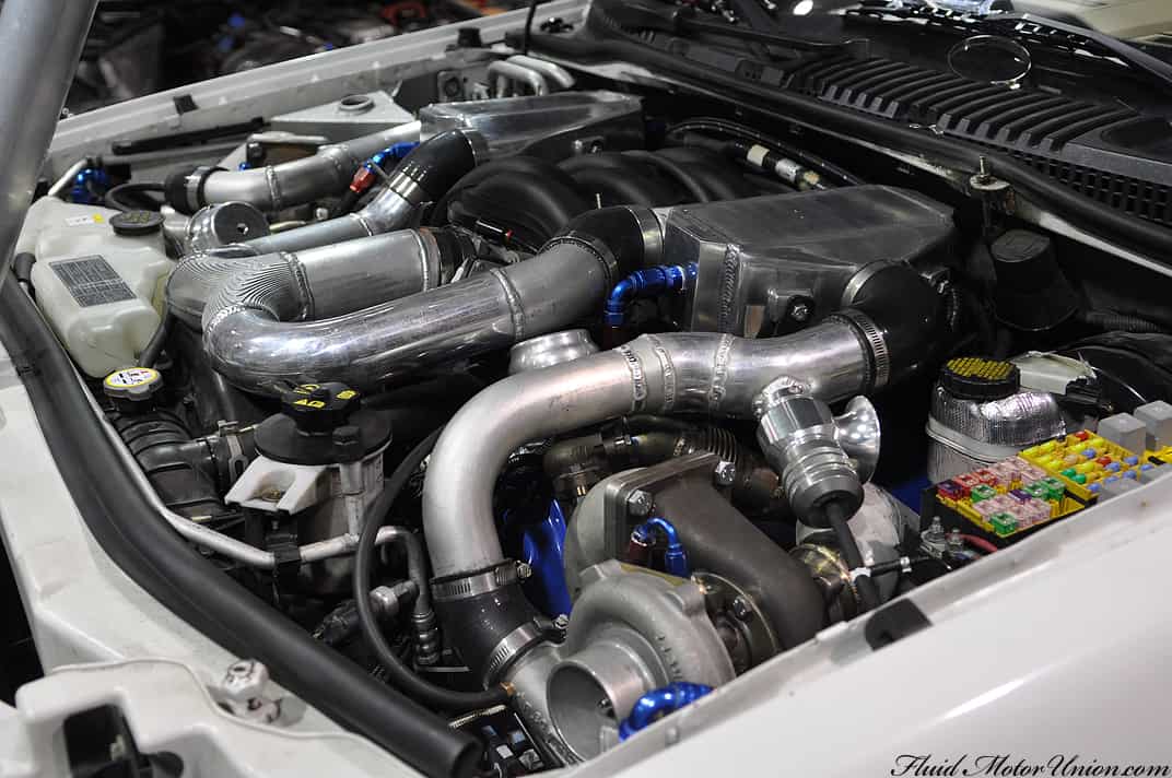
As everybody left for SEMA, the Explorer was fully assembled and ready to begin life doing dyno runs and adjusting the tune for both daily drivability and all-out ballsiness. While showing you a bunch of pictures of us doing algebra and filling in tables would be exciting for the DIY ECU enthusiast (and not much of anybody else), we figured we would forego those shots. Once we had the tune written enough to where dyno runs were possible, we strapped it to the dyno and slowly began running it, building in revs a little more with each subsequent run. And that’s when the Explorer exceeded our expectations by the aforementioned large margin.
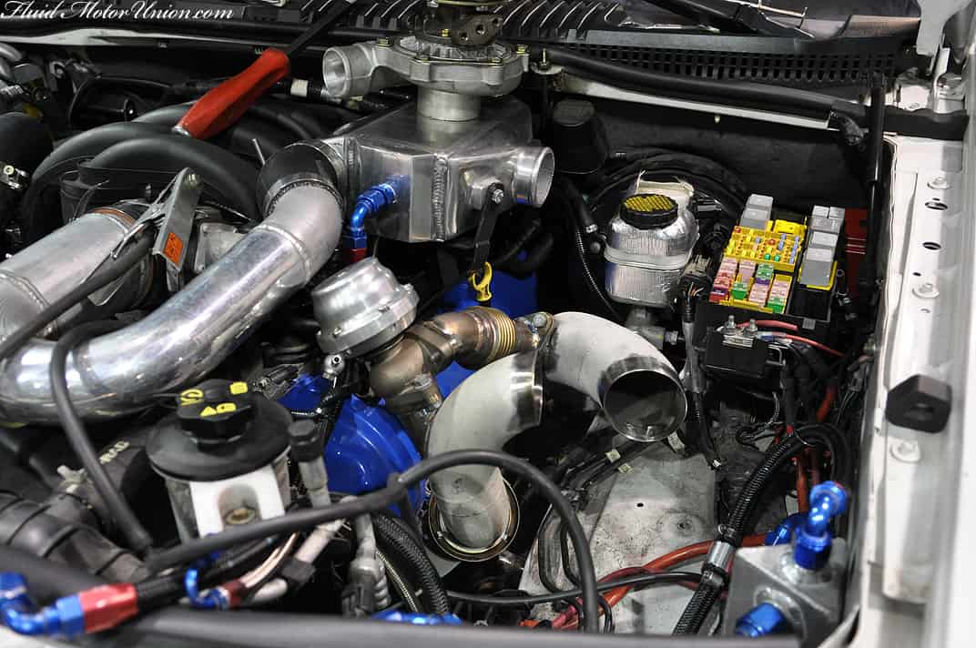
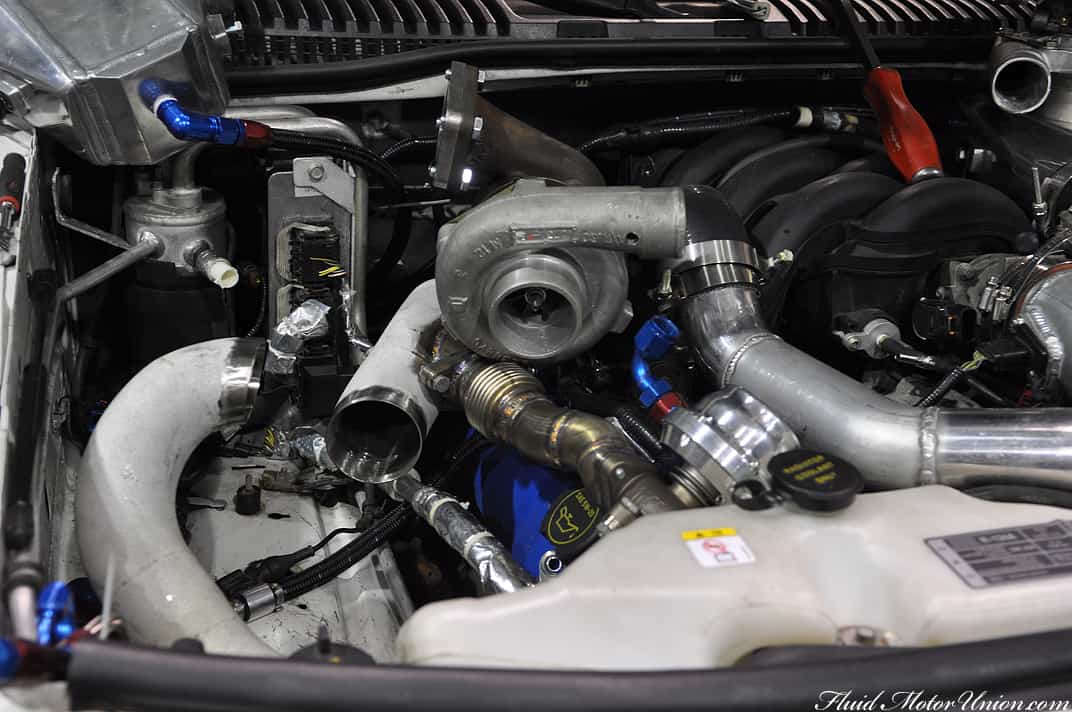
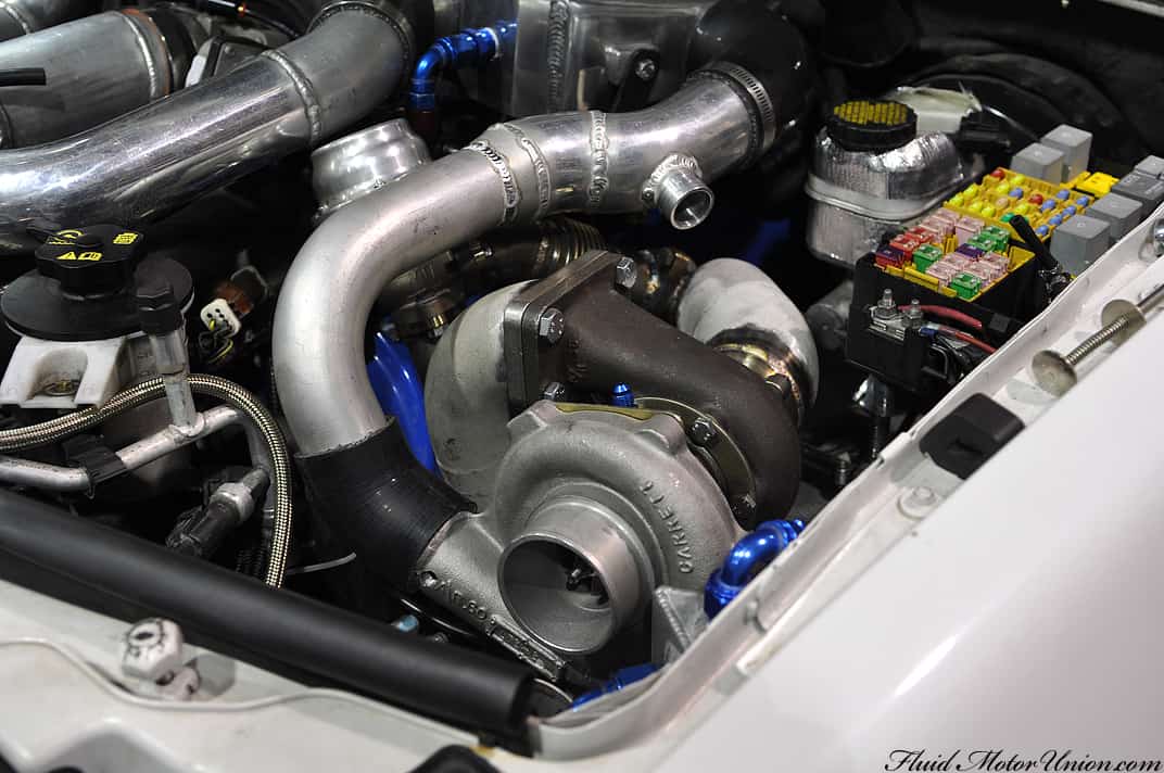
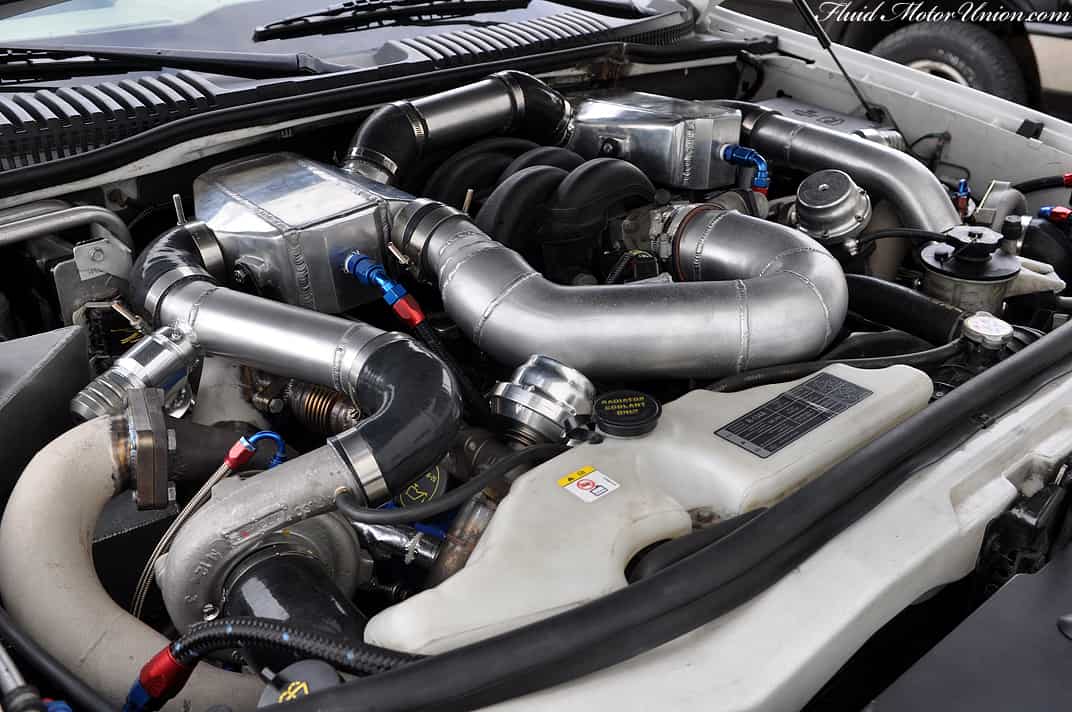
The twin VNT turbos were clearly excited to be attached to the Explorer’s Modular V8, as they decided to build more boost than Honda builds cars. The Explorer needs to boost to no more than 8-10psi for our desired safe levels of power, but instead, the snails were building 12-13 psi at approximately 3500 RPM (and climbing!!). One may see where an issue might lie. The response was absolutely nuts on this car, and boost would come on so rapidly that it seemed physically impossible to compensate for that large of a fuel swing so early in the table. Or was it?!
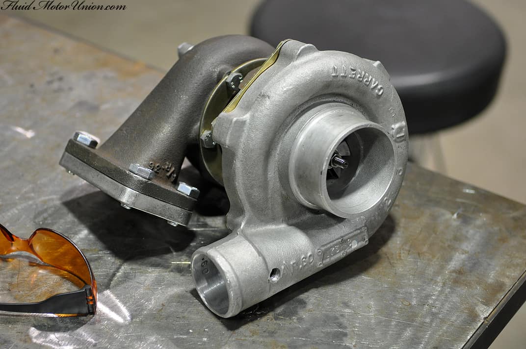
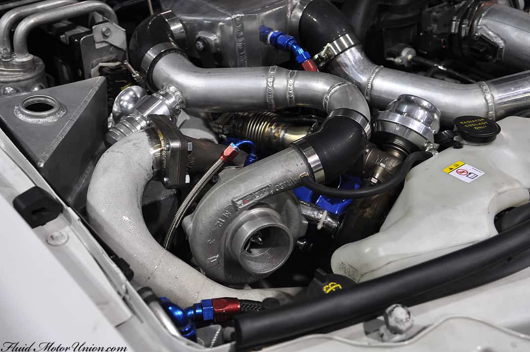
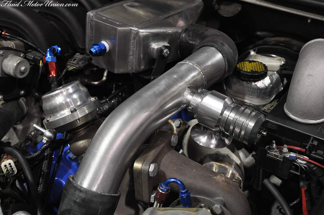
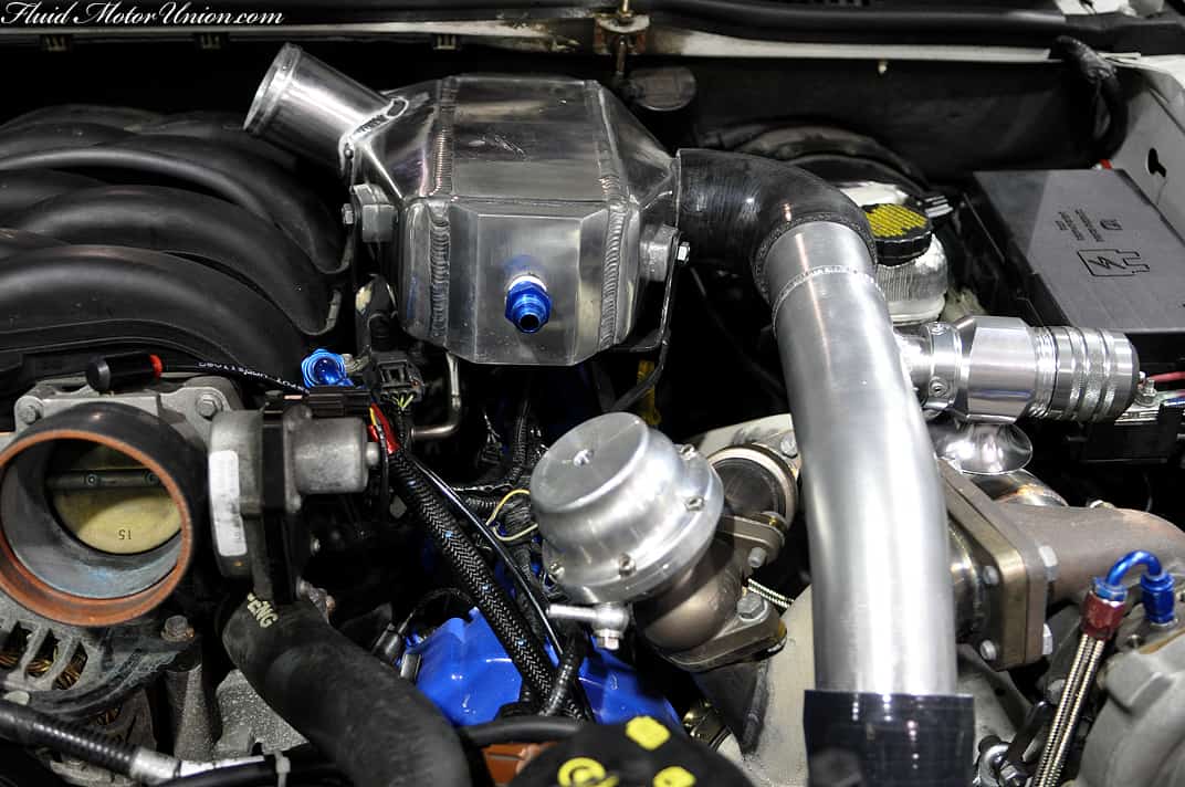
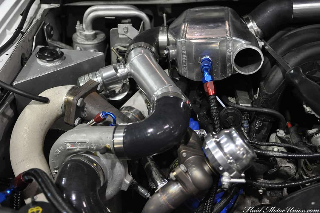
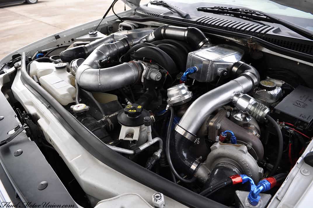
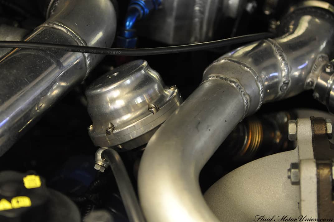
After a good amount of sitting and theorycrafting, the solution needed to be threefold attack on the problem. The first two steps (which aren’t covered by pictures in today’s blog) were a water-methanol injection system and a fuel pump booster. The third and final step was an alteration to the turbo system itself. In order to keep boost under control, we would need the help of some Tial external wastegates. Two of these guys, to be exact:
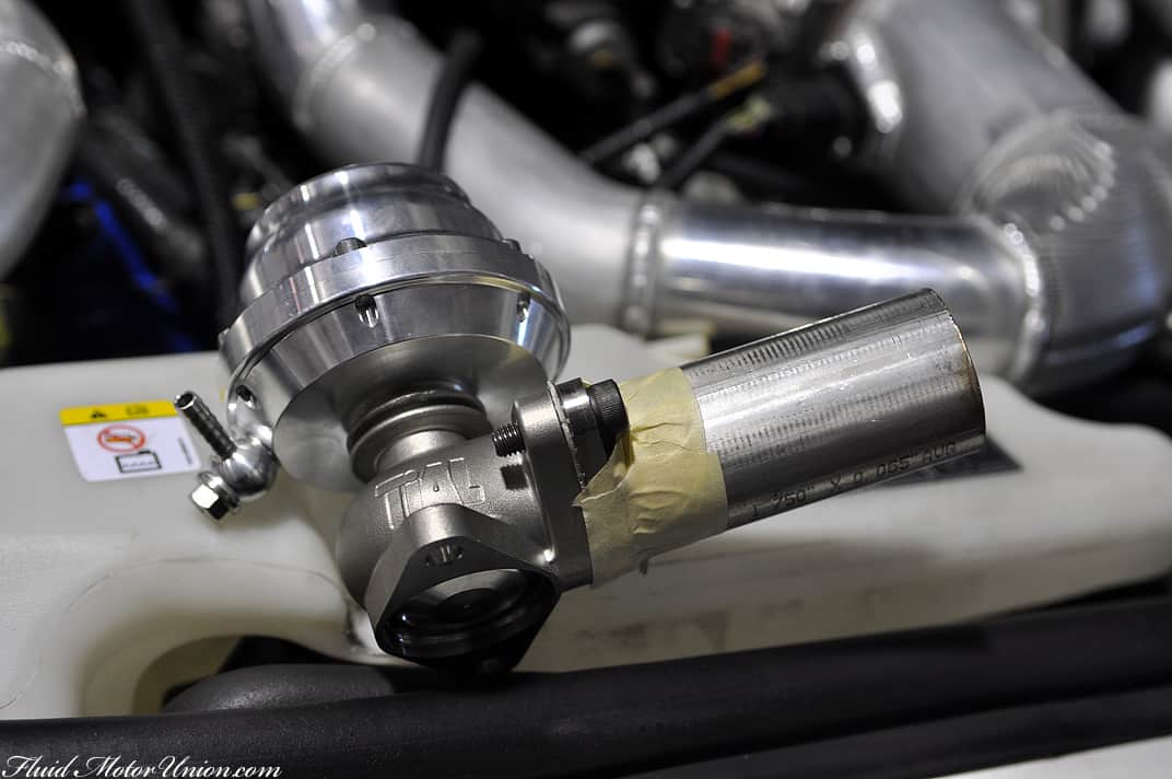
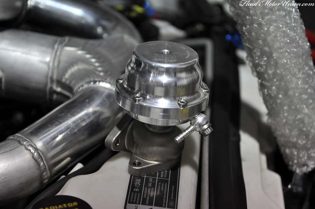
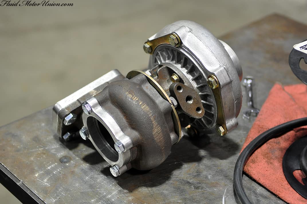
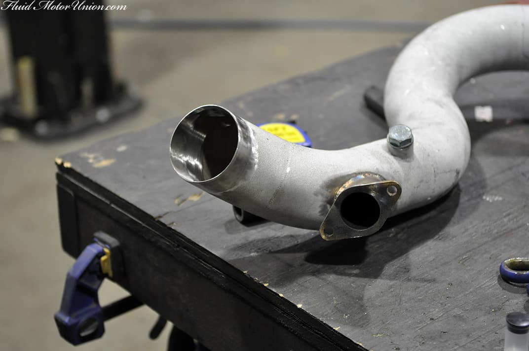
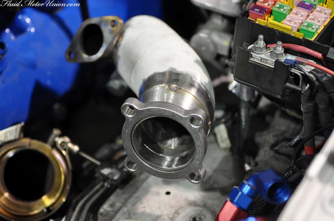
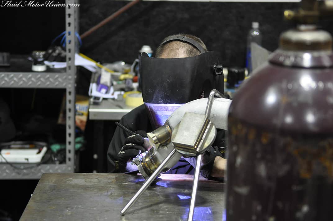
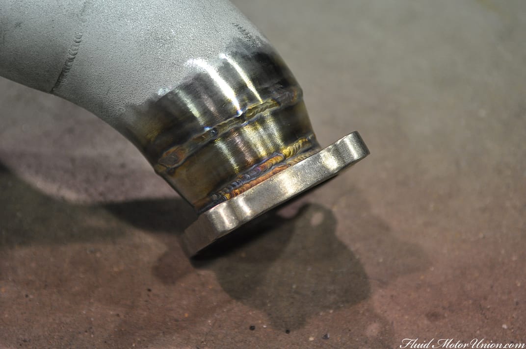
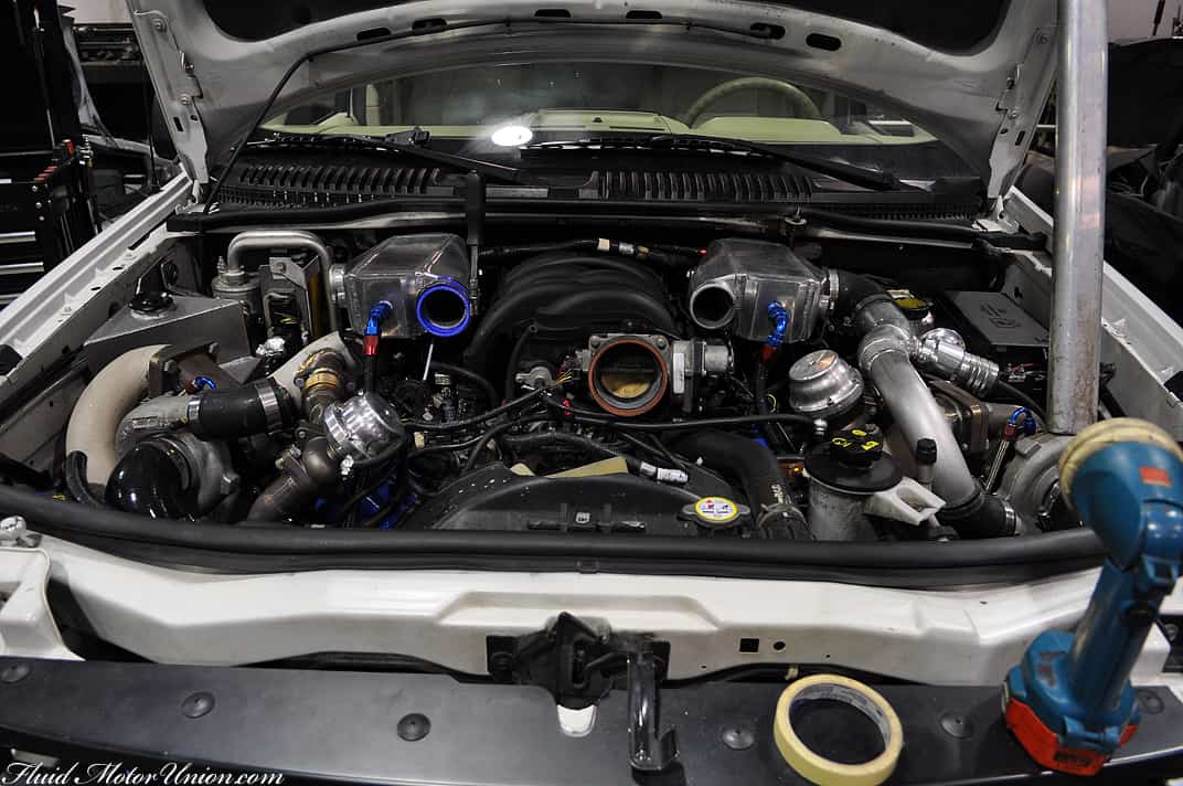
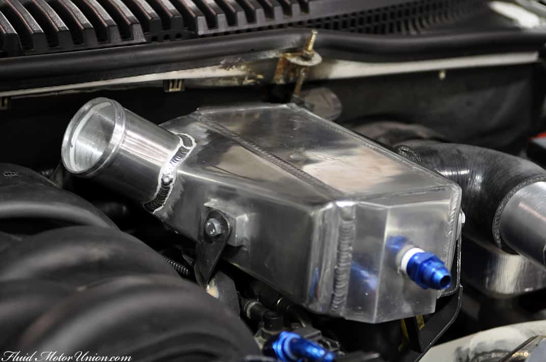
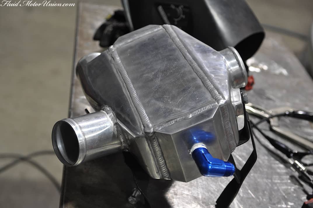
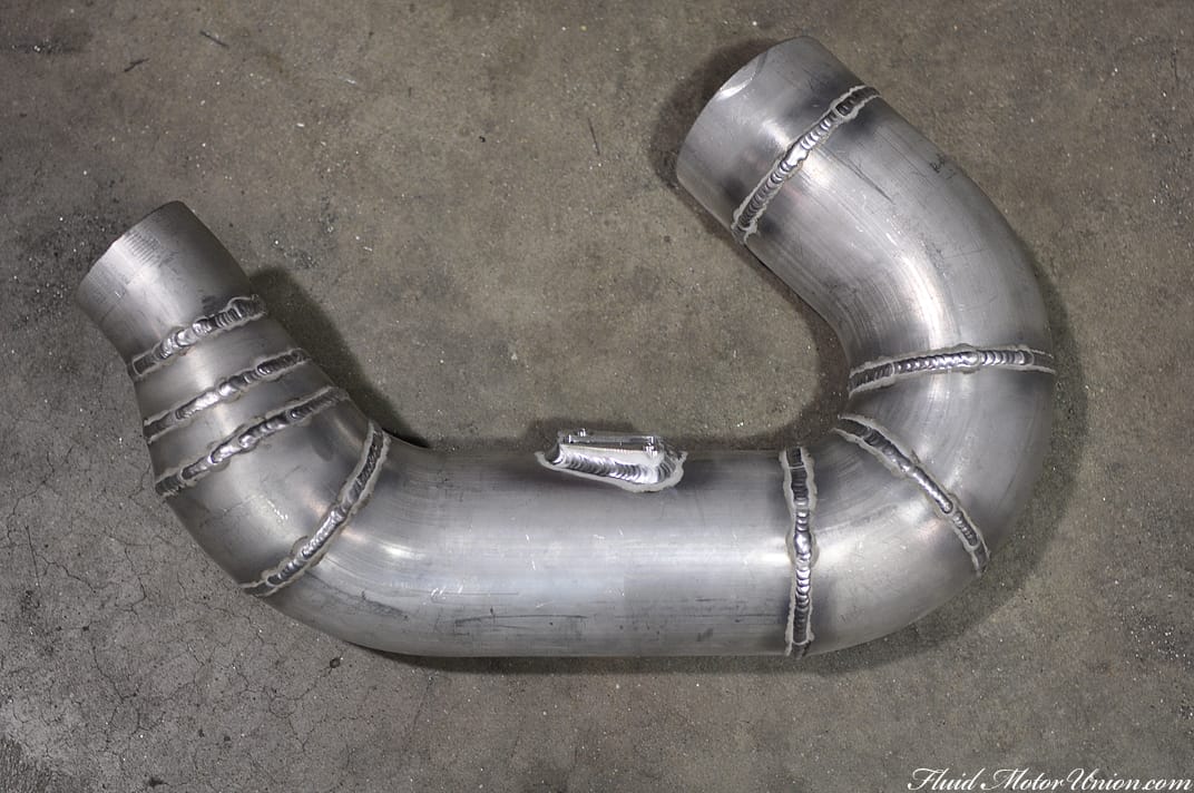
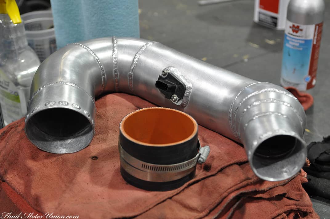
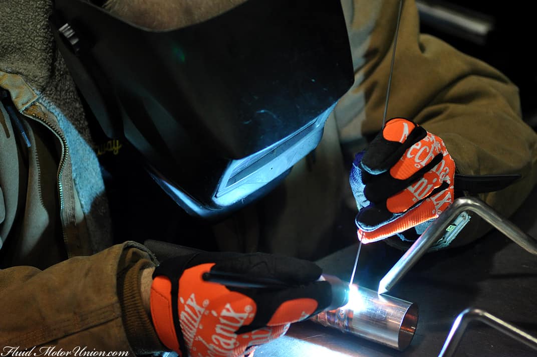
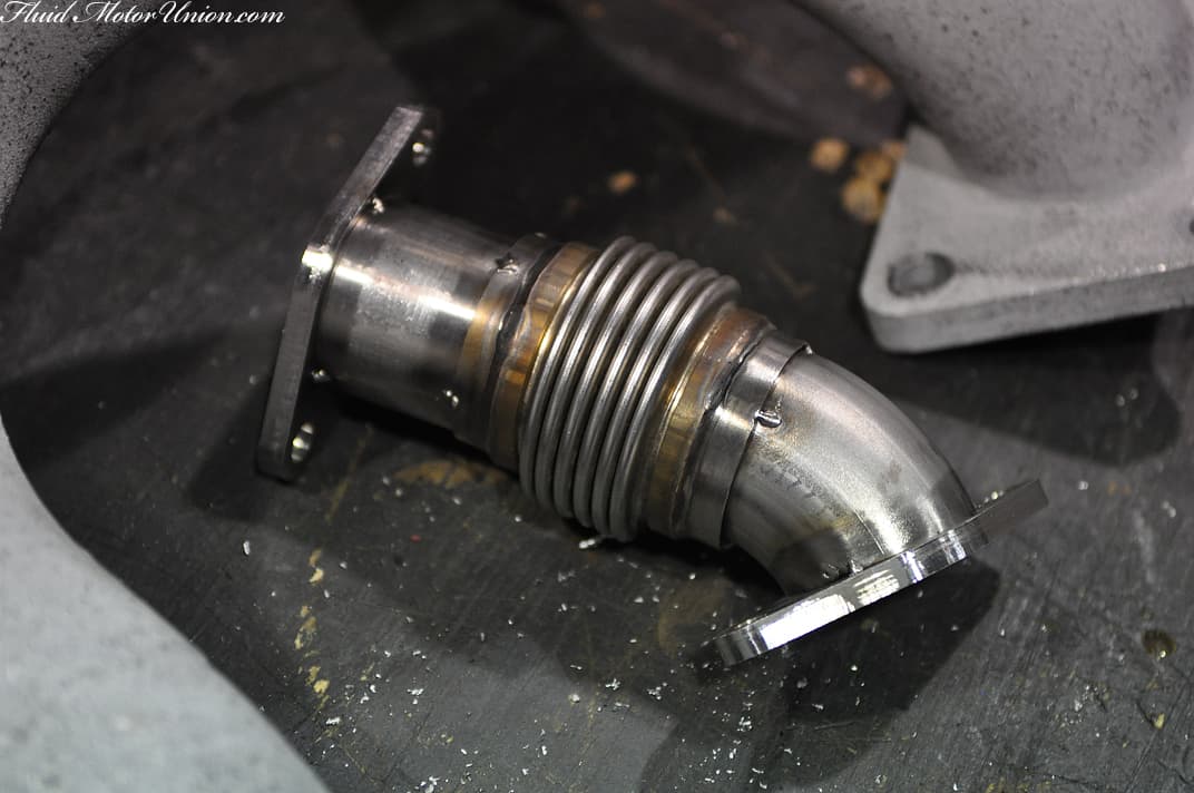
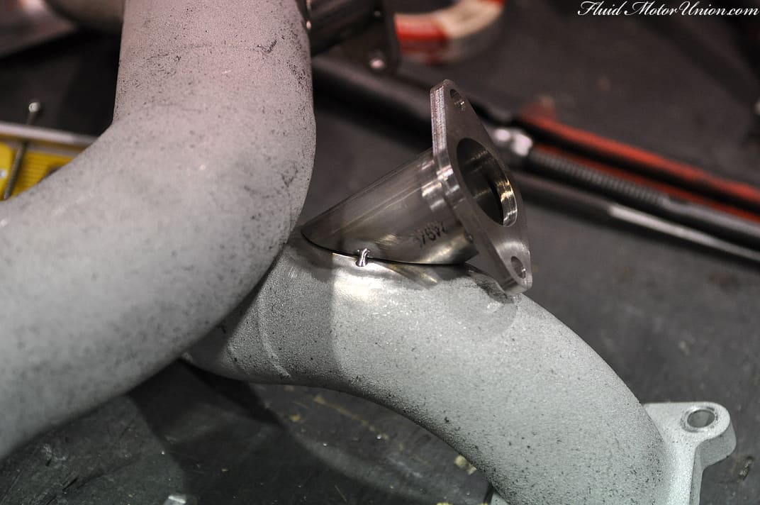
Obviously, one cannot just rest the wastegates inside the engine bay and call it a day. Given the fact that we managed to occupy almost every inch of available space when building the TT kit, we had to make sure fitment was precise, so nothing would interfere with anything else. We found a perfect spot on the downpipes, so we set about fabricating some new flanges from scratch, as well as creating the piping to connect the wastegates to the rest of the system. We had to remove a small bit of the Swain Tech coating from the pipes in order to get it to weld correctly, but the small amount of missing coating shouldn’t affect the overall heat retention properties of the system very much, if at all.
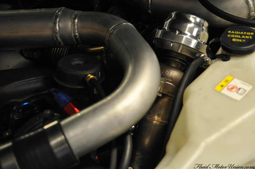
With the new water-meth, boost-a-pump and wastegates securely in place…
…It’s right back to work on the dyno, tweaking the tune bit by bit until we reach our desired outcome. Obviously the boost-building issues provided for a small setback, but as with any other vehicle modification that’s one-of-a-kind, issues may crop up from time to time. All we can say is that Scott and his wife have been nice enough to allow us to give in to our strict tenets of perfectionism, as we want nothing but success and reliability to come from this build. So we definitely owe them one big thank you, as well as everybody else in the automotive world that’s shown a great deal of interest in a build of this kind. Everybody’s eyes are on us, so the pressure’s definitely on. Videos will come soon, we promise!
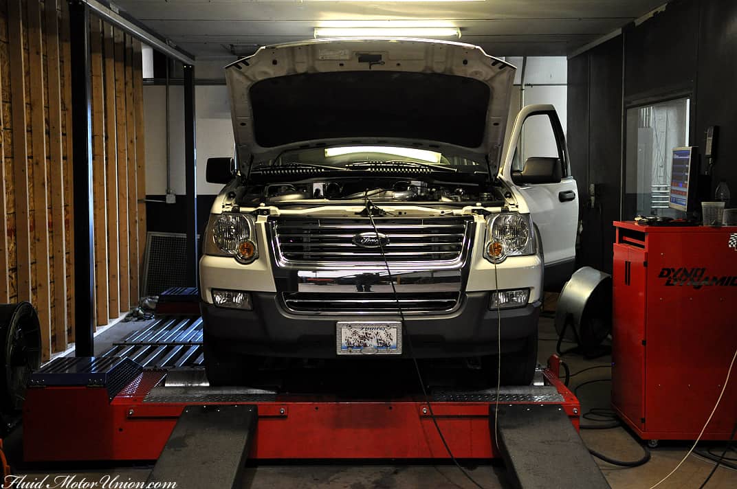
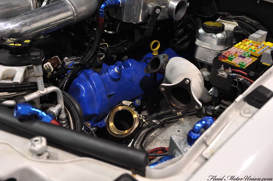
As everybody left for SEMA, the Explorer was fully assembled and ready to begin life doing dyno runs and adjusting the tune for both daily drivability and all-out ballsiness. While showing you a bunch of pictures of us doing algebra and filling in tables would be exciting for the DIY ECU enthusiast (and not much of anybody else), we figured we would forego those shots. Once we had the tune written enough to where dyno runs were possible, we strapped it to the dyno and slowly began running it, building in revs a little more with each subsequent run. And that’s when the Explorer exceeded our expectations by the aforementioned large margin.
The twin VNT turbos were clearly excited to be attached to the Explorer’s Modular V8, as they decided to build more boost than Honda builds cars. The Explorer needs to boost to no more than 8-10psi for our desired safe levels of power, but instead, the snails were building 12-13 psi at approximately 3500 RPM (and climbing!!). One may see where an issue might lie. The response was absolutely nuts on this car, and boost would come on so rapidly that it seemed physically impossible to compensate for that large of a fuel swing so early in the table. Or was it?!
After a good amount of sitting and theorycrafting, the solution needed to be threefold attack on the problem. The first two steps (which aren’t covered by pictures in today’s blog) were a water-methanol injection system and a fuel pump booster. The third and final step was an alteration to the turbo system itself. In order to keep boost under control, we would need the help of some Tial external wastegates. Two of these guys, to be exact:
Obviously, one cannot just rest the wastegates inside the engine bay and call it a day. Given the fact that we managed to occupy almost every inch of available space when building the TT kit, we had to make sure fitment was precise, so nothing would interfere with anything else. We found a perfect spot on the downpipes, so we set about fabricating some new flanges from scratch, as well as creating the piping to connect the wastegates to the rest of the system. We had to remove a small bit of the Swain Tech coating from the pipes in order to get it to weld correctly, but the small amount of missing coating shouldn’t affect the overall heat retention properties of the system very much, if at all.
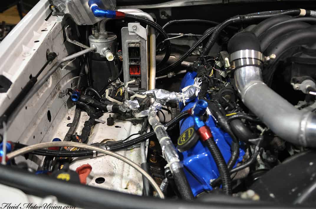
With the new water-meth, boost-a-pump and wastegates securely in place…
…It’s right back to work on the dyno, tweaking the tune bit by bit until we reach our desired outcome. Obviously the boost-building issues provided for a small setback, but as with any other vehicle modification that’s one-of-a-kind, issues may crop up from time to time. All we can say is that Scott and his wife have been nice enough to allow us to give in to our strict tenets of perfectionism, as we want nothing but success and reliability to come from this build. So we definitely owe them one big thank you, as well as everybody else in the automotive world that’s shown a great deal of interest in a build of this kind. Everybody’s eyes are on us, so the pressure’s definitely on. Videos will come soon, we promise!
 :
: