-
Performance Upgrades - Maintenance - Modifications - Problem Solving - Off-Road - Street Trucks.
Covering the Explorer, ST, Sport, Lincoln Aviator, Sport Trac,
Mercury Mountaineer, Mazda Navajo, Ford Ranger, Mazda Pickups, and the Aerostar.
Featuring H.I. - Human Intelligence.
Register Today It's free!
- Forums
- Generation Specific Forums
- 2002 - 2005 Explorer Mountaineer 3rd Generation
- Modified 2002 - 2005 Explorers
You are using an out of date browser. It may not display this or other websites correctly.
You should upgrade or use an alternative browser.
You should upgrade or use an alternative browser.
My 2004 Explorer
- Thread starter 4pointslow
- Start date
Elite Explorer members see no advertisements, no banner ads, no double underlined links,.
Add an avatar, upload photo attachments, and more!.
- Joined
- June 17, 2004
- Messages
- 24,265
- Reaction score
- 4,733
- City, State
- Knoxville, TN
- Year, Model & Trim Level
- 98 Limited AWD 302
...
Finished installing the intercooler pump switch and relay today.
Took it out for a ride. dropped the IAT 34 degree's from 180 to 146 at peak boost/rpm.
...
That's a much better level of IAT's. I like the idea of a low maintenance system, not having to add water or ice. I'm not after extreme levels, just a nice drama free rush, as needed.
- Joined
- June 17, 2004
- Messages
- 24,265
- Reaction score
- 4,733
- City, State
- Knoxville, TN
- Year, Model & Trim Level
- 98 Limited AWD 302
...
And shape and design are what is limiting me, what kind of air intake tube are you going to use?
I was aiming for a 90-100mm size of TB, but the oval units will be that big for sure. So the intake tube will end up being between that size and the MAF I can fit next to the air cleaner. I'd guess in the 3.5" range, the radiator hose and AC housing are nearby and the stock parts set next to things.
- Joined
- January 22, 2007
- Messages
- 10,154
- Reaction score
- 1,816
- City, State
- selkirk, manitoba
- Year, Model & Trim Level
- 98 supercharged 347 sport
Tim's maf (PMAS MH90 90mm Universal 3000) equivalent to the SCT-3000) see's a max airflow of 807.
tim also has a brand new spare one with pigtail for those who are interested

- Joined
- April 3, 2008
- Messages
- 3,273
- Reaction score
- 882
- City, State
- Gloucester City, NJ
- Year, Model & Trim Level
- 98 2Dr,2,000 & 04 4dr xlt
Yes and that design from PMAS(that Tim has) is a good one unlike the one I have with the slot style sensor that doesn't bolt on correctly.
- Joined
- April 3, 2008
- Messages
- 3,273
- Reaction score
- 882
- City, State
- Gloucester City, NJ
- Year, Model & Trim Level
- 98 2Dr,2,000 & 04 4dr xlt
Thanks for the help on the ltft's. I'll copy your work (using my maf transfer numbers) on the histogram as its a lot more fun doing that than the monotony of transposing numbers.
Just a note, don't use the data from the wot area from LTFT to adjust your tune for the WOT area.
The LTFT may be the last learned value from right before you hit the WOT area in the MAF transfer function.
And if you use STFT it wont work either, since STFT shows commanded A/F in lamda/lames (however you spell it).
For WOT you can add a user defined pid by right clicking the pid list in the datalog and creating a name like AF, then you make an equation in the box like
(analog in * 3 ) + 7.35
Then the datalog will display AF ratio
You can then make a histogram of AF vs maf counts to do the WOT area.
Please keep in mind these are half assed directions, including the equation. Feel free to ask questions if you have any.
My WOT area now seems to start at 613, and I am not using enough of my transfer function but that is ok because I may just change the pulley and add more boost sometime.
The below picture is of the AF vs maf counts
2000StreetRod
Moderator Emeritus
- Joined
- May 26, 2009
- Messages
- 10,597
- Reaction score
- 334
- City, State
- Greenville, SC
- Year, Model & Trim Level
- 00 Sport FI, 03 Ltd V8
John, you've made tremendous progress in the 9 months that I've been distracted with other activities (landscaping and politics) but then you've always been a very dedicated and capable automotive enthusiast while I'm just a "tinkerer". I'm impressed with the factory appearance of your engine bay.
- Joined
- April 3, 2008
- Messages
- 3,273
- Reaction score
- 882
- City, State
- Gloucester City, NJ
- Year, Model & Trim Level
- 98 2Dr,2,000 & 04 4dr xlt
Thanks Dale! I am glad to see you are back at working on your truck engine as well. We need more fast Explorers!
My next thing I guess is trying to keep it sounding factory too, but at the same time opening the exhaust a little.
This truck is quiet and I want to keep it that way.
My next thing I guess is trying to keep it sounding factory too, but at the same time opening the exhaust a little.
This truck is quiet and I want to keep it that way.
2000StreetRod
Moderator Emeritus
- Joined
- May 26, 2009
- Messages
- 10,597
- Reaction score
- 334
- City, State
- Greenville, SC
- Year, Model & Trim Level
- 00 Sport FI, 03 Ltd V8
I agree with the quiet performance option. My neighbor has a Jaguar F-type with selectable exhaust performance. She said when some kid pulls up next to her at a light and revs his engine, if there is no cop in sight sometimes she switches to high performance and blows him away. I considered electric actuator exhaust control for my Sport but the response was slow and the reliability was poor. It will probably be a couple years before I'm ready to upgrade my Centennial exhaust system. By then the technology will probably have significantly improved. Also, the longer body length increases my options.
- Joined
- April 3, 2008
- Messages
- 3,273
- Reaction score
- 882
- City, State
- Gloucester City, NJ
- Year, Model & Trim Level
- 98 2Dr,2,000 & 04 4dr xlt
Exhaust Back Pressure
I tested the exhaust back pressure and it pinned the gauge at 15 psi. Wow!
I was not expecting that.
Ford says no more than 8psi at WOT.
I plan to have some custom exhaust work done soon.
I tested the exhaust back pressure and it pinned the gauge at 15 psi. Wow!
I was not expecting that.
Ford says no more than 8psi at WOT.
I plan to have some custom exhaust work done soon.
- Joined
- June 17, 2004
- Messages
- 24,265
- Reaction score
- 4,733
- City, State
- Knoxville, TN
- Year, Model & Trim Level
- 98 Limited AWD 302
You aren't surprised, with having only one muffler? Find a way to fit two mufflers and tailpipes back there. Nobody really does that, but it will be quieter than one, and halve the resistance versus one.
- Joined
- February 18, 2009
- Messages
- 5,334
- Reaction score
- 618
- City, State
- Winnipeg, Manitoba
- Year, Model & Trim Level
- 04 Mustang GT
Its a pretty amazing thing that the factory can make big hp and still have a vehicle super quiet. I actually have a huge muffler and the turbo to quiet my exhaust. Its still loud, although the turbo whine seems to drown out the exhaust noise when I'm on the gas.
Tim's truck sounds like a modified motorcycle. lol.
I'll be interested in what you come up with.
Tim's truck sounds like a modified motorcycle. lol.
I'll be interested in what you come up with.
- Joined
- April 3, 2008
- Messages
- 3,273
- Reaction score
- 882
- City, State
- Gloucester City, NJ
- Year, Model & Trim Level
- 98 2Dr,2,000 & 04 4dr xlt
I was surprised that it hit 15 psi of back pressure and pinned the gauge. I did however expect slightly high back pressure, just not that high.
The 1998 with 1 muffler and lots more boost only hit 11lbs of backpressure before doing the dual exhaust.
Just got back from the exhaust shop and they say they can get a 3 inch single exhaust in there.
That should be good to about 337 HP at the crank.
I am having them cut the exhaust just after the Y, it is three inches there and will be 3 inches all the way back.
Also going with a Magnaflow absorption muffler this time. I had one on my Ranger and it was not too loud.
- Joined
- April 3, 2008
- Messages
- 3,273
- Reaction score
- 882
- City, State
- Gloucester City, NJ
- Year, Model & Trim Level
- 98 2Dr,2,000 & 04 4dr xlt
2004 Explorer Exhaust Restrictions
Here are some pictures of the 2004 Explorer 4.0L exhaust from my truck.
The front pipes seem large enough(first pic), I think they are 2.25 OD but for some reason I forgot to write them down so don't quote me on them.
Two 2.25 pipes should be able to flow enough for 184 HP per side, so a total of 368 (at crank).
I am using this statement found on the internet.
"Straight pipe is said to flow 115 CFM per square inch of area, to avoid exhaust restriction the exhaust pipe should flow 2.2 CFM per horsepower"
So the equation is-
Area Times 115 CFM / 2.2 CFM = Pipe supporting Horsepower
The stock HP from this engine is about 210 at crank, so they didn't need to flow a lot from the factory at WOT.
It is said that keeping the exhaust velocity fast will help with scavenging and keep low or mid range torque high.
Also as the exhaust flows down the pipes it starts to cool and that means the gases are condensing some.
By using some smaller diameters as you get further back on the exhaust system, keeps the velocity high.
However you can not make the exhaust so small that it causes restrictions for the amount of total HP the engine is making, or the back pressure will be too high. Ford says no more than 8psi at WOT. I have 15.
The first picture shows the y pipe, where they join it becomes 3 inches OD which would support 337 HP at the crank at WOT.
The second picture shows the first step down in size, it goes from 3 to 2.75 OD which would only support 282 HP at the crank at WOT.
The third picture shows where the "cat back" part of the system is attached, you can see how it steps down in size again. It is 2.25 OD.
2.25 would only support about 184 HP at the crank, makes me wonder why they would go that small and how much does the exhaust condense by the time it gets to that spot.
The wall thickness of the tail pipe was .0625, I assume the same for the rest of the exhaust.
My plan is to go three inch all the way back, that should allow up to 337 at the crank at WOT. I plan to retest exhaust back pressure after it is done. I also have no idea what HP this engine is making with the supercharger on it, yet.
2000StreetRod
Moderator Emeritus
- Joined
- May 26, 2009
- Messages
- 10,597
- Reaction score
- 334
- City, State
- Greenville, SC
- Year, Model & Trim Level
- 00 Sport FI, 03 Ltd V8
John, while exploring the front end did you notice a good location for a remote engine oil filter? I would like to install one that is fairly easy to access but would not interfere with an intercooler heat exchanger that might be installed in the distant future.
- Joined
- April 3, 2008
- Messages
- 3,273
- Reaction score
- 882
- City, State
- Gloucester City, NJ
- Year, Model & Trim Level
- 98 2Dr,2,000 & 04 4dr xlt
John, while exploring the front end did you notice a good location for a remote engine oil filter? I would like to install one that is fairly easy to access but would not interfere with an intercooler heat exchanger that might be installed in the distant future.
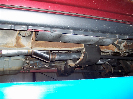
Try the Left front, take the small part of the wheel well out. It has 4 screws and two plastic push clips holding it on.
Maybe it would fit there? Same amount of space as the right front where I put the intercooler pump.
You probably could still access it through the bottom to change the filter?
On these 3rd gens, there seems to be more space in a lot of areas.
The bumper is really easy to take off too.
2000StreetRod
Moderator Emeritus
- Joined
- May 26, 2009
- Messages
- 10,597
- Reaction score
- 334
- City, State
- Greenville, SC
- Year, Model & Trim Level
- 00 Sport FI, 03 Ltd V8
The location of your intercooler pump seems optimum: sturdy mounting support (frame rail); protected by frame rail; and ample space. Is it hidden from view when the small part of the wheel well is installed? I could reserve that space for my intercooler pump if I ever get that far. On the driver side I could mount a remote engine oil filter and an electric oil pump.Try the Left front, take the small part of the wheel well out. It has 4 screws and two plastic push clips holding it on.
Maybe it would fit there? Same amount of space as the right front where I put the intercooler pump.
You probably could still access it through the bottom to change the filter?
On these 3rd gens, there seems to be more space in a lot of areas.
The bumper is really easy to take off too.
My 2002 shop manual mentions an optional engine oil cooler for the 4.0L. I don't see one on your 2004 but from my experience one isn't needed. I saw no mention of a transmission cooler. My 2002 shop manual lists a possible transmission oil cooler. Does your 2004 have one?
- Joined
- April 3, 2008
- Messages
- 3,273
- Reaction score
- 882
- City, State
- Gloucester City, NJ
- Year, Model & Trim Level
- 98 2Dr,2,000 & 04 4dr xlt
The location of your intercooler pump seems optimum: sturdy mounting support (frame rail); protected by frame rail; and ample space. Is it hidden from view when the small part of the wheel well is installed? I could reserve that space for my intercooler pump if I ever get that far. On the driver side I could mount a remote engine oil filter and an electric oil pump.
My 2002 shop manual mentions an optional engine oil cooler for the 4.0L. I don't see one on your 2004 but from my experience one isn't needed. I saw no mention of a transmission cooler. My 2002 shop manual lists a possible transmission oil cooler. Does your 2004 have one?
With the smaller part of the wheel well installed you can only see the very bottom of the pump, just the inlet nipple and hose. However with the wheel on you can not see anything unless you stick your head under the fender.
The only transmission cooler I have is the one in the radiator.
- Joined
- June 17, 2004
- Messages
- 24,265
- Reaction score
- 4,733
- City, State
- Knoxville, TN
- Year, Model & Trim Level
- 98 Limited AWD 302
Well John, it's time for you to add a trans cooler. That needs one badly for that power level. Add an external filter too, and a deeper pan if there is one. The extra fluid will help cooling a little as well. The V8 five speed has a thermostat built into it also, like the 5R55E?
Elite Explorer members see no advertisements, no banner ads, no double underlined links,.
Add an avatar, upload photo attachments, and more!.
- Joined
- April 3, 2008
- Messages
- 3,273
- Reaction score
- 882
- City, State
- Gloucester City, NJ
- Year, Model & Trim Level
- 98 2Dr,2,000 & 04 4dr xlt
IRS axle seal
I noticed a while back that the drivers side of the differential was wet and dirty. It looked like the seal was leaking where the CV shaft goes into the housing.
The seal design was changed a few times due to leaks that just kept coming back on the IRS design.
I located an updated seal on eBay and have had it sitting around for a few months. I was not in a hurry to replace it since the threads on the end of the CV shaft were very rusty due to the wheel design holding water/moisture under the center cap. I figured I might have to replace the CV shaft at worst, but I got lucky and was able to clean it up with a small wire wheel attachment on a cordless drill.
Any way the seal is replaced and I will keep an eye on it to make sure it stays dry.
The picture on the left is the old seal design and has a protector included for installation (so you don't damage the new seal).
The picture on the right shows the new seal design which is what I used. I did not have or use a protector when installing, the seal looked designed well enough that it would not be needed either. I took extra care to not damage the seal as well, installing the CV shaft as straight as possible until it went in all the way.
Featured images


Featured images
Similar Threads
- Replies
- 0
- Views
- 1,498
- Replies
- 5
- Views
- 1,776
- Replies
- 9
- Views
- 4,188