How to: - 1994 Head gasket replacement / engine pull | Page 11 | Ford Explorer Forums - Serious Explorations

  • Register Today It's free!

How to: 1994 Head gasket replacement / engine pull

Prefix for threads which are instructional.
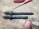
1-3. Old pistons. Getting replaced with the new Sealed Power pistons that have been WPC treated (at great expense). #6 has a good chunk loose on it if you look close. This wiggles when you touch it and I managed to pick the whole chunk out with my fingers. Probably from back when the truck was having issues with pinging. You can also see the side scuffing which several pistons had, and is my reason for replacement. The WPC treatment should reduce friction in this area though I am thinking it may have also been due to weak oil pressure feeding the squirters, and all the cold startups when it lived in AK. 20 below zero is hard on an engine.

From what I can tell, there's no reason to replace the connecting rods. It hasn't been abused or seen high RPM, they don't take wear directly (just the lower bearing, piston pin is press fit), and the bearings looked fine so they should be round. Keeping them.

I attempted to press one of the piston pins out with a friend's 12 ton press. The press wasn't up to the task and I wasn't going to risk damaging the new pistons, so I paid to have it done.

4-7. While I waited I've been cleaning brackets and painting them, and cleaning the other engine accessories. Fuel rail was cruddy and the aluminum was ugly. Scraped the majority of the burnt oil mist buildup off with a scraper. Went to town with a wire wheel on a Dremel at low speed, low pressure. Ended up doing the entire rail. Turned out very shiny and the surface took no damage. Curious how I can preserve this look or if I should paint the non-sealing surfaces black.

Undecided on replacing my fuel pressure regulator. Like my cam sensor it has gone 197k miles without fail; I don't want to install a replacement and risk it being defective out of the box or inferior quality.

WP_20161023_001res.jpg


WP_20161023_002res.jpg


WP_20161023_003res.jpg


WP_20161023_005res.jpg


WP_20161023_006res.jpg


WP_20161023_014res.jpg


WP_20161023_016res.jpg


Join the Elite Explorers for $20 each year.
Elite Explorer members see no advertisements, no banner ads, no double underlined links,.
Add an avatar, upload photo attachments, and more!
.


1-2. Crank, all clean and polished. Again, this is the factory crank which received a clean bill of health - everything is within spec and the bearings had almost no visible wear.
3. New rear main seal. Fel-Pro PTFE (Teflon). Hopefully a good design. Original seal had been replaced at some point. Light coat of oil before install.
4. Main upper bearings installed. Mahle/Clevite MS-2006A Bi-Metal. Added moly-fortified Engine Assembly Lube for pre-lube after picture was taken.
5. Dropped in the crank, installed new lower main bearings in caps. They tapped into place with minor effort. Spent some time aligning them. Ford has a specific method for aligning the thrust bearing - I hope I got it right. Caps all torqued to approx. 75 ft-lb.
6-7. All pistons installed.
Pistons are Speed Pro H570P hypereutectic for standard bore, with an added WPC coating. First verified they were assembled right - oil squirters squirt the wall of the cylinder toward the outside of the block. Notch in piston goes to front of engine. Rods are all numbered by cylinder (thanks Ford) and the numbers are on the caps as well. New Mahle/Clevite CB723P Tri-Metal rod bearings installed and pre-lubed. Rubber hose slid over rod bolt threads to avoid scratching cylinder walls on the way down. Cylinder bores cleaned a final time and oiled before piston install.

Rings are Sealed Power E-613K Premium Moly rings. Ring gap is approx. .025 with no filing; slightly beyond Ford's max .023 spec, but should be a huge improvement over the old rings, and I didn't overbore. Verified rings are not upside down. Oriented ring gaps so they're 180 degrees opposite each other. Used a ring compressor to squeeze them and tap the pistons gently into the bores. Once the rings were in the bore, pistons moved with some real resistance - it should seal well. Rod caps installed, torqued to approx. 21 ft-lbs.

8. Engine bagged back up. Two stretchy trash bags, tied on the far side. Before that, I set a dessicant bag on the center valley of the block to absorb moisture.

Comments?

WP_20161029_001res.jpg


WP_20161029_002res.jpg


WP_20161029_003res.jpg


WP_20161029_004res.jpg


WP_20161029_009res.jpg


WP_20161029_012res.jpg


WP_20161029_013res.jpg


WP_20161029_014res.jpg


All looks good.nice job and good details


so much for just changing the heads/gaskets.

very inspiring. great job1


I wanted to do this on mine, but got to the point I just wanted it up and running. Engine sure looks real nice dipped and painted.

Might look into having @Turdle powder coat some of the bolt on's (his work looks great and always nice to support a member.) I'd wanted to but it didn't work out. Always run out of time and money when you want something.


Thanks for all the kind words. It's been a personal challenge more than a mechanical one.

I had planned on local powdercoating for several parts but the business isn't the same since it changed owners. All I really need done is the lower intake and they don't do those any more since a customer claimed poor sealing afterwards (???) and raised hell. I've been keeping costs down by cleaning and painting parts instead but undecided on the intake so far. I may learn to port match it too.
Hmm thats odd..as long as its tapped up right and no powder gets on the mounting surface,i dont see how it would effect sealing..

Give porting and polish a try..just remember to start light,you can always go back and redo it once you get the feel down.ALOT can be removed from the lower.same with exhaust ports if you feel up to it.also a good polish on the combustion chambers helps prevent build up and detonation


Do you have a specific guide you recommend?


Do you have a specific guide you recommend?
I dont.
Just gasket match them and clean up cast marks,then a nice polish..i wouldnt go crazy.you get a feel for it after you get in it and couple ports done


1. Oil pump assembled with pickup and new pickup gasket. Primed first by pouring oil into the supply side and turning pump drive shaft clockwise until oil pumped out the outlet.

2. Installed oil pump and gasket. Drive shaft has to go in at the same time. Note which direction it goes - I marked mine during disassembly. On mine, the taper of the washer on the shaft pointed down.

3-4. Installed oil pan studs x2. I had marked with red paint which was the down side. Lacking the external torx socket, a 5/32" 6pt socket works fine.

5. Installing oil pressure sensor adapter, then oil pressure sensor (not pictured). I used Teflon tape on the threads to ensure a good seal. It's been said that this is a bad idea for sensors that ground through the mounting threads, but I've never had a problem with this on any sensor - there is still metal on metal. If I have an issue it's easy to fix even after the engine is installed.

6. Installing timing set. Pretty self explanatory. Timing marks on the gears need to be aligned as shown (picture is slightly crooked).

7. Per FSM, the torque required to rotate the assembly (pistons and all, measured at crank) should not exceed 33 ft-lbs. I was nervous but it passed the test. Simply set torque wrench to 33 ft-lbs and checked that it could rotate the assembly without clicking.

WP_20161111_003res.jpg


WP_20161111_004res.jpg


WP_20161111_005res.jpg


WP_20161111_006res.jpg


WP_20161111_008res.jpg


WP_20161113_001res.jpg


WP_20161113_003res.jpg


1. Took the rear main cap back off. Ford says to use anaerobic (cures in absence of air) sealer on the joints of it. I'm hoping I did the right spots but once removed it sort of makes sense. Had to pull the seal out again too as Ford states to align the cap with the block so that the seal will seat flush. This was tricky but I got it very close and re-torqued. EDIT: After re-assembly I have an oil drip from this area.

2. Re-installed windage tray/baffle.

3-4. Oil filter mounting gaskets, mount and bolt. The assembly has 3 O-rings. I managed to find two new ones. Hopefully my third (green one, goes on bolt) will be in good enough shape. Might be a dealer part otherwise. The mount has been soaking in Chem Dip for a couple days and came out nice. I don't plan to paint it since it wasn't painted from the factory and it won't rust anyways.

WP_20161113_004res.jpg


WP_20161113_005res.jpg


WP_20161117_005res.jpg


WP_20161117_006res.jpg


I have spent way too much time on this project cleaning parts...

1-2. The timing cover is finally ready for paint. Used to be black with grime. It has been washed with a hose and scrubbed, pressure washed, scrubbed in a sink, and finally gone over with a dremel brush. All the gasket surfaces have been cleaned up. I debated on grey like the block or black to hide grease. Masking it off was fun.

3. This is the paint used for the block.

4-5. Timing cover painted. I am considering detailing the letters in black, Ford emblem in blue. Just for fun.

6. Hardware ready for use after soaking in chem dip and scrubbing. Used to be solid grime color, covered in thick layers of grease and dirt. Now some of the fasteners look new. Crank sensor is the factory original Ford part. Cleaned up and ready to continue service.

WP_20161117_002res.jpg


WP_20161117_003res.jpg


WP_20161117_004res.jpg


WP_20161117_007res.jpg


WP_20161117_008res.jpg


WP_20161117_011res.jpg


Looking really good.

Just a reminder, Turdle does parts in powder coat...


1. Installed timing cover with new front seal. Used the old seal for reference of how deep to install. Ford makes a tool for this (like almost everything else) but of course I have to make do.

2. Without the Ford front cover alignment tool, I am doing the best I can. Lining up both sides of the timing cover with the bottom of the block gets me straight in at least one axis. EDIT: FWIW, this actually worked fine - I have not noticed any oil leakage after the rebuild.

3-4. There is room to install the crankshaft key. Per Ford I am using RTV in the keyway.

5. Installation of new harmonic damper. Pre-oiled seal and shaft. I heated the damper to 250 degrees Fahrenheit in the oven for 30 minutes and it easily pressed on part way. I installed the new main bolt (TTY) and the damper walked the rest of the way onto the shaft easily. Torqued it to spec, 30-37 ft-lbs plus 85 degrees additional rotation.

6. Oil pan gasket I'm using is a Fel-Pro Perma-Dry Plus. It is metal and synthetic rubber composite, and requires no RTV except for in corners and where the timing cover meets the block. It also has the updated rear main sealing design, that eliminated the separate "wedge seal" in 1994.

7. Installed oil filter adapter and new FL-1A filter. Only one of the seals I ordered ended up being correct.

8. Oil pan installed. Used straight edge to check that it was even with the rear of the block.

WP_20161123_002res.jpg


WP_20161123_004res.jpg


WP_20161123_005res.jpg


WP_20161123_006res.jpg


WP_20161123_007res.jpg


WP_20161123_008res.jpg


WP_20161123_009res.jpg


WP_20161123_010res.jpg


WP_20161123_011res.jpg


1. Thanks to JD4242's video tutorials I took my lifters apart for cleaning. Unfortunately I got halfway through them and then borked up some of the phenolic cups. Online research reveals the cups aren't necessary and are just for easier assembly line mechanics of guiding the pushrods in. I am not going to use them.

2. Installed all lifters.

3. Head gasket in place. Fel-Pro Perma-Torque Severe Duty.

4. Head surface.

5-8. Heads installed with new Morana bolts. For now they are torqued to the initial stage of 22 ft-lbs, prior to lower intake installation. Spark plugs (Autolite Double Platinum APP605) are installed and gapped to .054.

WP_20161123_015res.jpg


WP_20161123_016res.jpg


WP_20161123_018res.jpg


WP_20161123_013res.jpg


WP_20161123_019res.jpg


WP_20161123_020res.jpg


WP_20161123_021res.jpg


WP_20161123_022res.jpg


How did you get all this info? When I tore mine apart, I saw no mention of of the height of the timing cover seal or applying RTV to the keyway. I also didn't have to heat the harmonic balancer, it went on with the bolt without hardly any resistance. I used the factory crank bolt since I didn't know any better but found later that it's TTY. Been a year and haven't had an issue.

Also had no idea there was an updated oil pan gasket, seemed to me there was only the rubber one. When I installed it, I applied RTV around the outside, as a second seal since I don't trust Fel-Pro. The wedge seal was a pain, would have been nice to do away with that. A year on, mine still leaks from the rear but I don't know if I screwed up the rear main which wasn't leaking (installed a sleeve and SKF seal) or if it was the wedge seal or oil pan. Such a minor leak now compared to what it was, I don't let it get me down.

Are you using the 1994 FSM for this? What's the part numbers for the oil pan gasket you used?

Final question; when can you do mine? :)

Most of my info is from the Ford FSM on CD. 1994. Other info is from lots of reading online. Some is best guess common sense like trying to understand the intent of a Ford tool I dont have. Oil pan was a tricky one since the Ford FSM still states the wedge seal but reading articles from rebuilders online is where I learned about the running change (it all started when I tried to track down the wedge seal). Part number of the oil pan gasket is Fel-Pro OS 34309 R.

The rear main is a known leak spot and I hope I did mine right. It's easy to forget the anaerobic sealant for the main cap and there were issues with the seals sold aftermarket as well. Most are updated by now.


What a lucky break I have someone a few steps ahead of me as I am doing my own rebuild. I have been reading this whole thread, and I think the info here is fantastic. Its full of specific details you can't find anywhere else without major digging.


What a lucky break I have someone a few steps ahead of me as I am doing my own rebuild. I have been reading this whole thread, and I think the info here is fantastic. Its full of specific details you can't find anywhere else without major digging.

I wholly agree. I'll probably save this page as PDF when it's all done, I'll probably do this in the future. Thank you for sharing this wealth.


Join the Elite Explorers for $20 each year.
Elite Explorer members see no advertisements, no banner ads, no double underlined links,.
Add an avatar, upload photo attachments, and more!
.


Thanks for the kind words. Please note though that I'm no expert and I may be missing some things or making errors. Just doing the best I can within my budget of time and money.

Ideally I would have spent more time checking tolerances and replacing more items with new ones. Additionally I would track down more parts, like the Ford OEM timing cover gasket (instead of Fel-Pro) and oil filter adapter o-rings. Honestly for the amount I've spent I think I could have done a junkyard 5.0 conversion cheaper, but I have an attachment to this motor. This has all been a best case scenario with a very healthy motor allowing me to re-use things like heads, crank, lifters, and con-rods. A neglected motor might not be financially feasible to rebuild right.

Another thing I learned. When you are cleaning your oil pan, a pressure washer works well, but take the oil level sensor out first. $80 mistake. Tracking down a replacement was tricky but it seems that one made for a Mustang should work.
UPDATE: The sensor was fine. See post #232 for follow up and further info on replacement.


Back
Top