- Joined
- February 16, 2001
- Messages
- 5,418
- Reaction score
- 25
- City, State
- 43°48′48″N 91°13′59″W
- Year, Model & Trim Level
- 91 4 do'
On my 1991 Ford Explorer 4.0 OHV I decided to scrap my entire factory dash board for a simple bolt on aluminum dash. Unfortunatley I was unable to find any website out there that gave a detailed step by step and the sites I found with bits and pieces had dead picture links.
Here was my goal.
*replace factory gauge cluster with 5" Auto Meter Speedometer & Tachometer and 2 1/16" Auto Meter Voltmeter, Fuel, Oil Pressure & Water Temp gauges.
*reuse factory headlight switch, radio, push button 4x4.
* keep as much of factory wiring harness zip tied to firewall (just in case) but run new cable for my sending units for easy diagnosis. This way factory dash could still be hooked up if needed (not sure why, code checks, Check engine lights...it just made more sense than clipping a bunch of wires)
Parts list
Auto Meter 5" Speedometer #4495
Auto Meter 5" Tachometer #4498
Auto Meter 2 1/16" Voltmeter Gauge #4391
Auto Meter 2 1/16" Fuel Gauge #4318
Auto Meter 2 1/16" Oil Pressure Gauge #4327
Auto Meter 2 1/16" Water Temp Gauge #4337
In this write up I will mention toning, testing voltage and testing Ohms. In making this a complete crash course, I will explain each in my words
Toning- 2 piece tool, the toner and wand. The toner sends an audible signal through the wire. To identify (ID) the wire you start at the source (fuel wire at the tank) and clip on the toner, the wand is used to trace around where you need to identify the wire(the dash). When your tip touches the wire an audible signal will let you know that you have found the tone. In my line of work this is used often, imagine wiring an entire hotel with a pile of cables all pulling to one source. You would put the toner in a phone jack of a room on the 10th floor, go back to the phone room with the wand and sift through a pile of wires until you find the one that makes noise when your wand brushes over it, much faster than hooking a meter to each one.
Testing Voltage- fairly easy, but learning how to use a meter is crucial, set the meter to volts and when a positive and negative is completed the voltage will display. Spend time with a meter just playing around by your battery and you will see that it should read around 12 with the ignition off, 14.4-14.6 with the engine running if your alternator is working properly.
Testing Ohms- simlar to the toner, this helps with when you need to ID a circuit. Setting your meter to Ohms will display a "1", when you touch the positive and negative together of the meter it will "Zero Out" and display a "0". This means you have a circuit. This will help you trace a wire to the fuse panel etc. I just used my ohm tester on a fuse that didn't look blown but was, a good fuse should complete a circuit and "zero out" where a bad fuse will stay reading 1.
Step 1- Keeping your truck working without factory cluster
The truck will run fine without the factory cluster except 1 issue. The alternator needs a signal from a hot wire from the ignition to signal it to charge. On the alternator there is a harness, in this harness there is a green/red stripe wire that I was able to tone back to the stock cluster.
Pictured below is the alternator harness. Using a toner or Ohm meter you can trace this wire to the dash.

On the factory cluster there is 2 plugs after I identified the green/red stripe I attached that to a "hot" wire when the ignition is on to turn on the voltage regulator. You can see the connection with a blue connector. Also note the red wire and green/red strip both happen to be the second wire in on opposite plugs. I left just enough slack behind just in case I needed to reconnect.

Upon connecting these wires with a meter on the battery the voltage immediately jumped from 11.9 to 14.5 when the truck was running. Problem solved. I also tested that this wire was only hot when the ignition was on. Sources tell me that if you feed the green/red stripe a constant power source with the ignition off you will drain your battery.
Now that this is complete your truck will run normal with the factory dash unplugged. Not that I wanted to run without gauges, but I did for some time with no issues, prior to connecting this wire my battery would not charge.
Locate and wire "Signal" wires
The easiest method to tackling this big project was to pull each wire from the sending unit or signal wire of each function into the dash. I left plenty of slack and left the installation of the gauges until the very end. I have learned working with electrical, work from the outside in and it makes it very easy to accomplish your task.
The gauges have 3 leads (in most cases) ignition (+), ground (-), and signal(from sending unit).
Water Temp Gauge
I started here because I was able to find a little info online about the location. On the 4.0 motor the coolant sensor is located to the passenger side of the throttle body near the front of the motor. Removing the intake helped and I removed the factory sending unit. The Auto Meter sending unit looks similar to the Ford Unit but I left no chance.
Make sure you wrap the sending unit with Teflon tape prior to installing.
I used a socket with an extension and this was a breeze once I located the unit.

I used a blue wire and routed it in or along the factory loom and used an existing rubber grommet to lay this into the dash and labeled it for ease in the future.
Oil Pressure Gauge
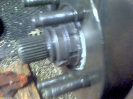
I referred to my Chilton's index to find the location of my factory oil pressure sending unit. This was a challenge to locate, but a good tip is to find the factory low oil sensor located just in front of your starter (held on with a 1 1/16" nut) and the oil pressure sending unit is grouped in the same wiring harness, wedging myself under my truck made it fairly easy to unbolt the factory sending unit. The factory sending unit is much smaller than the Auto Meter Oil Pressure Sending unit, I did not grab a photo due to leaking oil, but I found this photo, the Auto Meter unit is on the left.

You will use the NPT fitting and the larger diameter coupling and this installed with just enough clearance above my steering gear on my 1st generation. Here is a shot of the unit from above and below to help you locate it. Again use Teflon Tape for installation. Upon install, run a new wire to the dash as you did with the water temp gauge.
From the top

From the bottom (reference steering box)

Fuel Level Gauge
The Ford Explorer fuel pump has a built in sending unit for fuel level. Fuel gauges work off Ohms, in this instance a full tank of gas reads 145 ohms, an empty tank of fuel reads 22 ohms, as you use fuel your ohm level drops moving the needle of the gauge. Auto Meter sells several configurations, in our instance part number 4318 reads Empty/ Full, 16 Ohms/ 158 Ohms. This was as close as it gets and reads accurate in my opinion.
The last 2 gauges mentioned I ran new wire from the sending unit to the dash. In this instance, I tested and found the yellow/white stripe on the factory plug was used for the fuel level. Looking at the back of the cluster, it resembles the Auto Meter gauge with a label of S(signal), I(+), N(-) and several light bulbs on a circuit board.
Double checking my work, I toned out the wire from the fuel tank (I had a spare fuel pump/ sending unit to ID the wire so it was easy, otherwise one would need to drop the tank to make this discovery) to the dash as well as ohm tested the Signal wire from the factory cluster. In the photo I was not on the correct point for the fuel gauge, but this shows testing to "zero out" a circuit where I will use the matching wire from the plug for my new signal wire.

finding the yellow/white was the 3rd prong over on the dash, it used the matching wire and made my connection to a new signal wire leaving slack to run my new harness.

Voltage gauge
This requires no signal so I will touch on this when I wire the gauges. I will mention that wiring a signal wire will give you a 18+ voltage signal...Don't ask me how I know this. I even got smart and made a sexy jumper wire instead of pulling in an additional signal wire, unfortunately this wasnt necessary and actually made my gauge inaccurate, so you can just wait on the voltage until later.

Again, that is incorrect, but I found this on other forums as well. Your voltmeter does not need an additional signal wire to function.
Speedometer
Fairly simple, I went to a local speedo shop to have a new cable built, the factory style connection will not work. Make sure you get the correct length and output for your transmission/transfer case end of this as well.
Tachometer
I found this with the help of Maniak from this site, using a signal wire that is wired on the passenger side near the fire will a tan/yellow stripe with a quick plug connector works just fine for your signal wire. I cut off the white plug and crimped on a new wire.
 (again that is passenger side rear, my truck has no hood so don't let the pic fool you). Again run the signal wire under your dash and you've now completed the hard part.
The fun part, new guages going in
Here are a few pics of my dash with the wires going in. Auto Meter tells you that you need a 2 1/16" hole saw (I found mine at Ace) and a 4 5/8" hole saw (I couldn't find one) so I used a 4 1/2" and used a hand file to increase the size of the opening. I also used a jig saw and a drill to drill out my cutouts for my radio and push button 4x4.
dash from the rear

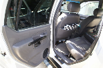
side work (showing the craftsmanship before hacking it apart, a very nerve-racking process might I add)

cutting in the radio

and push button 4x4 (note, I outlined the lines and used a jig saw to connect the dots)

Lining up my small guages first, I centered 2 over the steering column and marked dead center for each gauge while double checking the distances. Measure twice cut once theory applied here. Check your height from a reference point (I used bottom of dash) distance between holes (to make sure your spacing will be universal) and distance from center after you mark the dots. I drew circles to make sure it looked like it would make sense. I left a 1" gap between the gauges (therefore two halfs of a 2 1/16" gauge is ironically 2 1/16" and 1" gap means my center drilled holes are 3 1/16" apart).
disregard the circle drawings, I was mocking that up while the dash was in the truck to see how it would fit.

Then cut your holes out

I still didn't believe Auto Meter required a 4 5/8" hole saw, living in the Phoenix metro area we are a pretty big city and I couldn't find that anywhere. I was nervous about using a router or a grinding bit because the outer lip on these gauges doesn't leave anything for margin of error. Sure enough after sizing it with my micrometer I saw 4 5/8" and you can also see the small outer lip on this gauge.

I used a 4 1/2" hole saw and what felt like an hour with a hand file making the speedo and tach fit in place.

Now the fun part, the guages all get mounted

very simple on the back, a sleeve slides over and they tighten down with 2 nuts each.

Wiring
This is where I will give a short sermon on wiring, I have gotten very comfortable with wiring big projects recently. Just taking baby steps and keeping things organized keeps everything running smooth.
I decided that I was going to use a molex style connector to make removing the dash easy. I'm not really sure why I want my dash to be quick removable, but it's been handy thus far so why tie it down with a bunch of wires. A molex connection will be right under the headlight switch and will look very similar to this.

In this case I realized that each gauge has 1 light (2 on tach and speedo) with a black and white wire coming out of them.
Starting with the gauge closest to the passenger side, I daisy chained the wires (2 in, one out) making a common path for the positive and ground for the illumunation. I used an adhesive mount for a zip tie to keep this secured to the dash. There is no easy way to avoid a spaghetti mess of wires, so the easiest thing to do is control what you can.

you can see on the black wire how I tied each gauge together.

I left about a 1 foot tail after the last gauge to tie into my connector. To be really trick, the blue/red strip wire on your headlight switch controls illumination. I will be wiring my gauges to this lead and will have full dimmer controls.

Now you need to repeat the same process with the ignition power. I found the largest cable in the original dash plugs and tested with key on and off with my volt meter to determine that it will be my source of power for my gauges. Sorry, I don't have a photo, but I think it was a gray/yellow stripe on the factory dash plug. Using this will keep it in the same positions on the fuse panel.
Going back to the gauges, you will wire these with the same "daisy chain" fashion that the illumination lamps were wired.
On the back of each gauge there is a S N I labeled with a terminal and/or a spade connector, I used red wire and connected each "I" together, a black wire for each "N" and then used white cable for each "S". Bringing these all to the end, I ended up with 8 cables coming from the gauges, power/ground for Ill, power/ground for gauge power, signal ("S") for water, oil, fuel, tach, remember, speedo is mechanical, voltage is a simple gauge that uses the power to measure voltage.

I labeled each and put blade connectors prior to going through the trouble of a Molex connector. This picture looks like a nightmare, but it is just laid out for simplicity when I was lining up everything back in the truck. When I mount them to a molex connector, I will tidy up everything and use plenty of zip ties and loom.
It has been brought to my attention that this picture below looks like ass. To reitterate, I used a molex connector, this was just used for the testing before I put it all in single plug in harness.

That is pretty much it. Everything is working fine, speedo cable gets picked up tomorrow and I should have the molex connector on as well.
Again, I will zip tie the unused wiring harness back to the dash and enjoy my new dash. I realize that I can expand more if I wish. I currently have no check engine light, blinker indicators, or other warning lights on my dash, but I like the new look and it's good to know how another part of my truck functions when I'm stranded in the desert someplace.
Here was my goal.
*replace factory gauge cluster with 5" Auto Meter Speedometer & Tachometer and 2 1/16" Auto Meter Voltmeter, Fuel, Oil Pressure & Water Temp gauges.
*reuse factory headlight switch, radio, push button 4x4.
* keep as much of factory wiring harness zip tied to firewall (just in case) but run new cable for my sending units for easy diagnosis. This way factory dash could still be hooked up if needed (not sure why, code checks, Check engine lights...it just made more sense than clipping a bunch of wires)
Parts list
Auto Meter 5" Speedometer #4495
Auto Meter 5" Tachometer #4498
Auto Meter 2 1/16" Voltmeter Gauge #4391
Auto Meter 2 1/16" Fuel Gauge #4318
Auto Meter 2 1/16" Oil Pressure Gauge #4327
Auto Meter 2 1/16" Water Temp Gauge #4337
In this write up I will mention toning, testing voltage and testing Ohms. In making this a complete crash course, I will explain each in my words
Toning- 2 piece tool, the toner and wand. The toner sends an audible signal through the wire. To identify (ID) the wire you start at the source (fuel wire at the tank) and clip on the toner, the wand is used to trace around where you need to identify the wire(the dash). When your tip touches the wire an audible signal will let you know that you have found the tone. In my line of work this is used often, imagine wiring an entire hotel with a pile of cables all pulling to one source. You would put the toner in a phone jack of a room on the 10th floor, go back to the phone room with the wand and sift through a pile of wires until you find the one that makes noise when your wand brushes over it, much faster than hooking a meter to each one.
Testing Voltage- fairly easy, but learning how to use a meter is crucial, set the meter to volts and when a positive and negative is completed the voltage will display. Spend time with a meter just playing around by your battery and you will see that it should read around 12 with the ignition off, 14.4-14.6 with the engine running if your alternator is working properly.
Testing Ohms- simlar to the toner, this helps with when you need to ID a circuit. Setting your meter to Ohms will display a "1", when you touch the positive and negative together of the meter it will "Zero Out" and display a "0". This means you have a circuit. This will help you trace a wire to the fuse panel etc. I just used my ohm tester on a fuse that didn't look blown but was, a good fuse should complete a circuit and "zero out" where a bad fuse will stay reading 1.
Step 1- Keeping your truck working without factory cluster
The truck will run fine without the factory cluster except 1 issue. The alternator needs a signal from a hot wire from the ignition to signal it to charge. On the alternator there is a harness, in this harness there is a green/red stripe wire that I was able to tone back to the stock cluster.
Pictured below is the alternator harness. Using a toner or Ohm meter you can trace this wire to the dash.
On the factory cluster there is 2 plugs after I identified the green/red stripe I attached that to a "hot" wire when the ignition is on to turn on the voltage regulator. You can see the connection with a blue connector. Also note the red wire and green/red strip both happen to be the second wire in on opposite plugs. I left just enough slack behind just in case I needed to reconnect.
Upon connecting these wires with a meter on the battery the voltage immediately jumped from 11.9 to 14.5 when the truck was running. Problem solved. I also tested that this wire was only hot when the ignition was on. Sources tell me that if you feed the green/red stripe a constant power source with the ignition off you will drain your battery.
Now that this is complete your truck will run normal with the factory dash unplugged. Not that I wanted to run without gauges, but I did for some time with no issues, prior to connecting this wire my battery would not charge.
Locate and wire "Signal" wires
The easiest method to tackling this big project was to pull each wire from the sending unit or signal wire of each function into the dash. I left plenty of slack and left the installation of the gauges until the very end. I have learned working with electrical, work from the outside in and it makes it very easy to accomplish your task.
The gauges have 3 leads (in most cases) ignition (+), ground (-), and signal(from sending unit).
Water Temp Gauge
I started here because I was able to find a little info online about the location. On the 4.0 motor the coolant sensor is located to the passenger side of the throttle body near the front of the motor. Removing the intake helped and I removed the factory sending unit. The Auto Meter sending unit looks similar to the Ford Unit but I left no chance.
Make sure you wrap the sending unit with Teflon tape prior to installing.
I used a socket with an extension and this was a breeze once I located the unit.
I used a blue wire and routed it in or along the factory loom and used an existing rubber grommet to lay this into the dash and labeled it for ease in the future.
Oil Pressure Gauge
I referred to my Chilton's index to find the location of my factory oil pressure sending unit. This was a challenge to locate, but a good tip is to find the factory low oil sensor located just in front of your starter (held on with a 1 1/16" nut) and the oil pressure sending unit is grouped in the same wiring harness, wedging myself under my truck made it fairly easy to unbolt the factory sending unit. The factory sending unit is much smaller than the Auto Meter Oil Pressure Sending unit, I did not grab a photo due to leaking oil, but I found this photo, the Auto Meter unit is on the left.
You will use the NPT fitting and the larger diameter coupling and this installed with just enough clearance above my steering gear on my 1st generation. Here is a shot of the unit from above and below to help you locate it. Again use Teflon Tape for installation. Upon install, run a new wire to the dash as you did with the water temp gauge.
From the top
From the bottom (reference steering box)
Fuel Level Gauge
The Ford Explorer fuel pump has a built in sending unit for fuel level. Fuel gauges work off Ohms, in this instance a full tank of gas reads 145 ohms, an empty tank of fuel reads 22 ohms, as you use fuel your ohm level drops moving the needle of the gauge. Auto Meter sells several configurations, in our instance part number 4318 reads Empty/ Full, 16 Ohms/ 158 Ohms. This was as close as it gets and reads accurate in my opinion.
The last 2 gauges mentioned I ran new wire from the sending unit to the dash. In this instance, I tested and found the yellow/white stripe on the factory plug was used for the fuel level. Looking at the back of the cluster, it resembles the Auto Meter gauge with a label of S(signal), I(+), N(-) and several light bulbs on a circuit board.
Double checking my work, I toned out the wire from the fuel tank (I had a spare fuel pump/ sending unit to ID the wire so it was easy, otherwise one would need to drop the tank to make this discovery) to the dash as well as ohm tested the Signal wire from the factory cluster. In the photo I was not on the correct point for the fuel gauge, but this shows testing to "zero out" a circuit where I will use the matching wire from the plug for my new signal wire.
finding the yellow/white was the 3rd prong over on the dash, it used the matching wire and made my connection to a new signal wire leaving slack to run my new harness.
Voltage gauge
This requires no signal so I will touch on this when I wire the gauges. I will mention that wiring a signal wire will give you a 18+ voltage signal...Don't ask me how I know this. I even got smart and made a sexy jumper wire instead of pulling in an additional signal wire, unfortunately this wasnt necessary and actually made my gauge inaccurate, so you can just wait on the voltage until later.
Again, that is incorrect, but I found this on other forums as well. Your voltmeter does not need an additional signal wire to function.
Speedometer
Fairly simple, I went to a local speedo shop to have a new cable built, the factory style connection will not work. Make sure you get the correct length and output for your transmission/transfer case end of this as well.
Tachometer
I found this with the help of Maniak from this site, using a signal wire that is wired on the passenger side near the fire will a tan/yellow stripe with a quick plug connector works just fine for your signal wire. I cut off the white plug and crimped on a new wire.
The fun part, new guages going in
Here are a few pics of my dash with the wires going in. Auto Meter tells you that you need a 2 1/16" hole saw (I found mine at Ace) and a 4 5/8" hole saw (I couldn't find one) so I used a 4 1/2" and used a hand file to increase the size of the opening. I also used a jig saw and a drill to drill out my cutouts for my radio and push button 4x4.
dash from the rear
side work (showing the craftsmanship before hacking it apart, a very nerve-racking process might I add)
cutting in the radio
and push button 4x4 (note, I outlined the lines and used a jig saw to connect the dots)
Lining up my small guages first, I centered 2 over the steering column and marked dead center for each gauge while double checking the distances. Measure twice cut once theory applied here. Check your height from a reference point (I used bottom of dash) distance between holes (to make sure your spacing will be universal) and distance from center after you mark the dots. I drew circles to make sure it looked like it would make sense. I left a 1" gap between the gauges (therefore two halfs of a 2 1/16" gauge is ironically 2 1/16" and 1" gap means my center drilled holes are 3 1/16" apart).
disregard the circle drawings, I was mocking that up while the dash was in the truck to see how it would fit.
Then cut your holes out
I still didn't believe Auto Meter required a 4 5/8" hole saw, living in the Phoenix metro area we are a pretty big city and I couldn't find that anywhere. I was nervous about using a router or a grinding bit because the outer lip on these gauges doesn't leave anything for margin of error. Sure enough after sizing it with my micrometer I saw 4 5/8" and you can also see the small outer lip on this gauge.
I used a 4 1/2" hole saw and what felt like an hour with a hand file making the speedo and tach fit in place.
Now the fun part, the guages all get mounted
very simple on the back, a sleeve slides over and they tighten down with 2 nuts each.
Wiring
This is where I will give a short sermon on wiring, I have gotten very comfortable with wiring big projects recently. Just taking baby steps and keeping things organized keeps everything running smooth.
I decided that I was going to use a molex style connector to make removing the dash easy. I'm not really sure why I want my dash to be quick removable, but it's been handy thus far so why tie it down with a bunch of wires. A molex connection will be right under the headlight switch and will look very similar to this.
In this case I realized that each gauge has 1 light (2 on tach and speedo) with a black and white wire coming out of them.
Starting with the gauge closest to the passenger side, I daisy chained the wires (2 in, one out) making a common path for the positive and ground for the illumunation. I used an adhesive mount for a zip tie to keep this secured to the dash. There is no easy way to avoid a spaghetti mess of wires, so the easiest thing to do is control what you can.
you can see on the black wire how I tied each gauge together.
I left about a 1 foot tail after the last gauge to tie into my connector. To be really trick, the blue/red strip wire on your headlight switch controls illumination. I will be wiring my gauges to this lead and will have full dimmer controls.
Now you need to repeat the same process with the ignition power. I found the largest cable in the original dash plugs and tested with key on and off with my volt meter to determine that it will be my source of power for my gauges. Sorry, I don't have a photo, but I think it was a gray/yellow stripe on the factory dash plug. Using this will keep it in the same positions on the fuse panel.
Going back to the gauges, you will wire these with the same "daisy chain" fashion that the illumination lamps were wired.
On the back of each gauge there is a S N I labeled with a terminal and/or a spade connector, I used red wire and connected each "I" together, a black wire for each "N" and then used white cable for each "S". Bringing these all to the end, I ended up with 8 cables coming from the gauges, power/ground for Ill, power/ground for gauge power, signal ("S") for water, oil, fuel, tach, remember, speedo is mechanical, voltage is a simple gauge that uses the power to measure voltage.
I labeled each and put blade connectors prior to going through the trouble of a Molex connector. This picture looks like a nightmare, but it is just laid out for simplicity when I was lining up everything back in the truck. When I mount them to a molex connector, I will tidy up everything and use plenty of zip ties and loom.
It has been brought to my attention that this picture below looks like ass. To reitterate, I used a molex connector, this was just used for the testing before I put it all in single plug in harness.
That is pretty much it. Everything is working fine, speedo cable gets picked up tomorrow and I should have the molex connector on as well.
Again, I will zip tie the unused wiring harness back to the dash and enjoy my new dash. I realize that I can expand more if I wish. I currently have no check engine light, blinker indicators, or other warning lights on my dash, but I like the new look and it's good to know how another part of my truck functions when I'm stranded in the desert someplace.
 By the way. I love your dash