Supplementary alternator wiring: 4.0 SOHC | Ford Explorer Forums - Serious Explorations

  • Register Today It's free!

Supplementary alternator wiring: 4.0 SOHC

aldive

Elite In Memoriam
Joined
January 17, 2001
Messages
24,667
Reaction score
28
Year, Model & Trim Level
1999 XLT
Since I was having potential charging issues at idle speed after the install of my underdrive pulley ( http://www.explorerforum.com/forums/showthread.php?t=152040&highlight=underdrive ), I decided to do a “Big 3” ( alternator B + terminal to positive battery terminal, negative battery terminal to frame, frame to motor ) wiring upgrade prior to more drastic measures such as either a new 200 amp alternator or swapping to an overdrive alternator pulley ( http://underdog-performance.com/index.html ).

This installation was on my 4.0 SOHC but would be comparable on the other motors.

My plan was to add supplementary 4 gauge wiring to my 130 amp alternator to help the electrons freely flow.

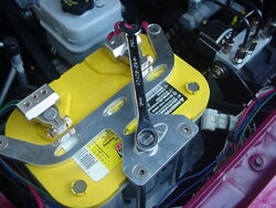
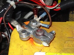
I added a new red 4 gauge wire from the B+ terminal of the alternator to the battery ( Optima Yellow Top ) and also added 4 gauge black grounds from the negative terminal of the battery to the frame as well as a 4 gauge black wire from the frame to the alternator bracket bolt.

The wire was purchased from West Marine ( http://westmarine.com/ ) for $3.69 per foot and the terminals at $4.85 for a pack of 2.

I measured the wire runs and cut the wire to the appropriate lengths and crimped on the terminals.

The wire from the B+ alternator terminal to the positive battery terminal was routed from the alternator under the upper intake and over to the positive battery terminal.

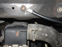
The new ground from the negative battery terminal to the frame was routed down below the battery to the driver’s side frame. After thoroughly sanding the area the terminal was bolted in place.

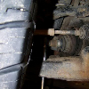
The new ground wire ( from the passenger side frame to the two upper alternator mounting bolt ) was routed down to the frame. After thoroughly sanding the area the terminal was bolted in place.

Idle voltage reading at the battery before the new wiring was 12.8 volts and after the install it was 12.8 volts; no improvement.

Even though this mod did not solve my low voltage at idle problem, it is a worthy mod for any application and essential with high output alternators. The installation took about 1 hour to complete and cost about $55.00.

It looks like an overdrive alternator pulley is next on my list.
 

Attachments

  • 2.jpg
    2.jpg
    51.4 KB · Views: 5,359
  • 5.jpg
    5.jpg
    25.9 KB · Views: 5,151
  • 1.jpg
    1.jpg
    61.2 KB · Views: 5,731


Join the Elite Explorers for $20 each year.
Elite Explorer members see no advertisements, no banner ads, no double underlined links,.
Add an avatar, upload photo attachments, and more!
.


Sounds good. I'm going with some more and larger wiring on my build thread.


Wow that seems pricey, $3.70 a foot?
I will ahve to look here in CO and see if its lower (pretty sure it is)

I assume you left the factory cables in place as well as adding these on top (piggyback)? The cable that grounds the frame also goes on to ground the engine block on the 4.0L OHV and 5.0L trucks I have worked on.

Does the SOHC also have a wire that goes from the + bat terminal to the fender mount starter solenoid? this is the + feed for the whole truck basically, the power distribution box is fed this way and then on to the interior fuse panel. Did you upgrade this wire as well if equipped?

I would consider die electric grease and heat shrink over those crimped connections, corrosion will get in there.
I use an old finger from a thick rubber glove to protect my alternator + post.
Where does your gage pick up voltage? at the battery or at a fuse panel?

Looking good, nothing ventured nothing gained, right?
I am sure you helped out an aging factory wiring harness amd witht he new HO alternator you should be golden! ;)


Correct me if I am wrong
If you are measuring 12.8 volts at the Batt, at idle, you have zero output from the alt.
Most that have installed the ASP UD have only seen a voltage drop of approx 2/3 tenths of a volt.


You should be running at least 14.25 volts at the batt, at idle, have you measured the alt output? should be with the UD about 14.1
 

Attachments

  • Mvc-030s.jpg
    Mvc-030s.jpg
    63.4 KB · Views: 4,942


Damn Spindle how close do your battery terminals come to that billet Optima holder? In that pic it looks a little too close for comfort!


410Fortune said:
Damn Spindle how close do your battery terminals come to that billet Optima holder? In that pic it looks a little too close for comfort!
spookey close :eek:
bout a 1/4 inch


spindlecone said:
spookey close :eek:
bout a 1/4 inch

I'll say, leave it up to 410 to notice those kinda things LOL. Even if you remove the negative cable first it seems the wrench could still make contact with the grounded holder on the Pos. side. Sorry I'm just bored, had to say somthing. Hope a wet grasshopper or some metal does not come into contact with that pos. side and the holder.


Seems like an odd design for a hold down to me???

I do like your terminals however. I have had the best luck with these types, I do solder the ends of the wires I feed in there and then lock in with the set screw. I have had corrosion in there and make up a bad contact. I also use die electric around the opening and sometimes the liquid electrical tape like Rookie to help out the connection.

1/4" is close! I would be afraid of the two terminals touching each other if the battery were to shift, but then in my BII the battery gets bounced around a bit :)


No worrys
The billet holdown is bolted to the plastic OEM tray, no GRND.
Yep, tin the wires and hex um down, makes a great connection
 

Attachments

  • Mvc-030s.jpg
    Mvc-030s.jpg
    53.9 KB · Views: 4,948


I was worried about the two posts shorting out against each other, not your wrenching skills.

Does that sucker even conduct electricity?


410Fortune said:
I was worried about the two posts shorting out against each other, not your wrenching skills.

Does that sucker even conduct electricity?
Yep it conducts elec, it is aluminum.
The bottom portion of the holdown is milled to the exact config, of the Optima Batt.
Even if the entire assmbley were to become loose in the plastic OEM tray, the batt will not shift


Spindle is correct, if you only have 12.8VDC at idle then your alt is not charging at all. In my opinion (as an EE for Delco Remy for the last 8 years) an under drive alt pulley is not a good idea on anything. The VERY small gain it gives you is not worth the voltage loss to vital accessories in a modern EFI vehicle. The UD crank pulley is fine but I would never use the Alternator or water pump pullies on anything. I had several bad experiences with these from owning many mustangs in the past.

BTW- a 200amp alternator will not fix your charging problems Al. You are not just lacking current (Amperage) the voltage is not there because your regulator is not turning on at all. The UD pulley has slowed down the rotor so much that it's not spinning the alternator fast enough to even excite the internal regulator. Most likely a high amp alternator will have a higher regulator activation speed than what your stock alt does due to the rewound stator and rotor. Do yourself a favor and put the stock pulley back on your stock alt and things will be the way they were.


Green
Good post, But will not going to a larger Alt pully increase the speed of the Alt back to say what it was orig.Thats the intent is it not?


Green98XLT said:
BTW- a 200amp alternator will not fix your charging problems Al. You are not just lacking current (Amperage) the voltage is not there because your regulator is not turning on at all.

Do yourself a favor and put the stock pulley back on your stock alt and things will be the way they were.

The alternator is charging just fine except at idle. At engine speeds over 1000 RPMs, the voltage is fine.

I put the stock pulley back on and the voltage is very similar ( and responds to RPMs in a similar fashion ).


spindlecone said:
Green
Good post, But will not going to a larger Alt pully increase the speed of the Alt back to say what it was orig.Thats the intent is it not?

A larger in diameter pulley is underdriving, to overdrive or return to "normal", one needs a smaller diameter pulley.


Spindle- When you underdrive an alternator you install a larger diameter pulley which in turn slows down the alternator. This is opposite of the underdrive crank pulley which is always smaller in diameter.

If you've ever seen a cup car or any other alternator from a race car you will notice the pulley is HUGE to slow the alternator down when the engine is spinning 9K. I've seen cup car pulleys as large as 5 inches, the alt doesn't even charge until the motor is revved above 3500rpm!

Al- if you want to get your alternator spinning back at normal speeds (factory) you will now need an overdrive pulley (smaller diameter) due to your much smaller crank pulley.


Your correct green, always willing to learn.
The thing I do not understand about als problem at idle is that plenty of people have installed UDs on sporttracs and have seen minimal drop in alt output, a few tenths of a volt max.
What is always reported is that the UD pully lowers the engines idle, which I believe should be about 700 RPM warm.
If 700 is optimal, could even say a 50 RPM drop cause the alt to not output?
Maybe al is right on the cusp of output from the Alt at idle.
In another post by al he reports 12.4 volts at idle, 13.5 above 1200 rpm.
Maybe it is just a low idle problem, dunno


Yep, its just low idle. Once you get above ~1000rpm it charges just fine. The UD pulleys do not affect engine idle speed whatsoever, they just affect the accessories rotation speed. Underdrives will slow the accessories and overdrive will speed them up.

Most of your IR ford alternators have an excitation speed of approximately 900rpm rotor speed, so if you have a 2:1 pulley ratio (stock for the EX) then the engine only has to turn 450rpm to achieve this. If you install U/D crank pullies as well as U/D alt pulleys as Al has, he has brought the pulley ratio way down so the engine has to now turn ~1200rpm in order to reach that 900rpm alternator rotor speed. Makes sense?


Join the Elite Explorers for $20 each year.
Elite Explorer members see no advertisements, no banner ads, no double underlined links,.
Add an avatar, upload photo attachments, and more!
.


The installation of the UDP/Harmonic balancer did not change my idle at all. nor should it have.

It idles at 750 RPM.

My idle voltage has always been less than 14 volts except on a cold start up. when it is 14.1-14.3 volts.

At speed, the voltage has always, as it is now, about 13.4 volts.


Back
Top