SOHC V6 Timing Chain Saga | Page 14 | Ford Explorer Forums - Serious Explorations

  • Register Today It's free!

SOHC V6 Timing Chain Saga

Primary chain components

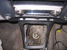
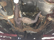
Today I installed the new jackshaft chain, tensioner, guide, and crankshaft and jackshaft sprockets as shown below.
Primary.jpg

I made sure that both camshaft sprockets are seated correctly on the camshafts but their retaining bolts are still loose so the sprockets can spin. The next step would be to torque the jackshaft front and rear sprocket retaining bolts but I haven't yet decided on my process without the special timing tools. I noticed that the left camshaft will stay by itself in the approximately correct position. However, the right camshaft will rotate approximately 50 degrees off because at the correct position the valve springs for cylinder #2 are almost completely depressed. I plan to test my "custom camshaft position holder" before I tighten the torque-to-yield bolts.


Join the Elite Explorers for $20 each year.
Elite Explorer members see no advertisements, no banner ads, no double underlined links,.
Add an avatar, upload photo attachments, and more!
.


When you have all of the chains on, that's when I'd begin with the jackshaft bolts. Those are the most troublesome to tighten because of the torque process and being able to hold them.

What do the manuals say to tighten first? Of course the crank and cams need to be very nearly at TDC always, everyone should keep remembering that. Nobody wants to turn one of the three unintentionally and start bending valves.

FYI, I highly recommend that you mark the bolt heads which need to be turned a certain number of degrees. Mark them when you reach the initial torque figure, and then a mark from there to where they need to turn to finish. It's been a long time since I did mine, it was interesting.


Hey Dale, just a suggestion when it comes to reinstalling your motor. Get a lift sling and wrap it around the exhaust manifolds and back around to the top. It will help balance and angle the motor for correct installation. Make sure it's long enough to make the complete loop around everything.
PRS3-yel_LRG.jpg


Assembly instructions

The engine assembly instructions are to:

1. Position the primary chain, crankshaft and jackshaft sprocket
2. Install the primary chain guide
3. Install the primary tensioner, release pin
4. Using special tool to hold the crankshaft torque the jackshaft front sprocket retaining bolt
5. Using special tool to hold the crankshaft torque the jackshaft rear sprocket retaining bolt
6. Install jackshaft rear plug
7. Install front timing cover

I want to time and torque everything (if possible) before installing the cover and plug.


looking at these pics of that sludge build up has me interested in all the oil flush type products you can buy. it would be cool to have a handful of engines that are sludged up like that and then run each one with a different kind of oil flush and see which one works the best!


Pill bottle camshaft holder

Before I can time the camshafts I need a tool to hold the camshafts in the correct position. The photo below shows what I came up with.
PilStrip.jpg

I used an Xacto knife to cut the ends off a small pill bottle with about the same inside diameter as the camshaft journals. Then I used tin snips to cut the remaining tube into 0.5 inch wide strips. Then I cut each strip slightly less than half of the diameter.
I removed the camshaft bearing caps and installed each strip on the journal as shown in the photo below making sure that the length of the strip was less than the exposed journal surface.
Strips.jpg

Then I loosely reinstalled the bearing caps. I did this for all four bearings since I did not want to risk bending the camshaft and I wanted as much friction surface as possible.


I decided to inspect the condition of the crankshaft journal and bearing farthest from the oil pump. The photo below shows the #1 crankshaft journal that appears to be in fairly decent condition after 10 years and 150,000 miles.

The width of the plastigauge indicates a clearance of .003 inches. I repeated the plastigauge test near the bottom of the journal next to the oil hole and the indicated clearance was slightly less than .002 inches. I believe that the bearings will last for another 10,000 miles.

Street Rod (Dale) did you mean to say the bearings will last another 100,000 miles? The difference in clearances that you have noted may be due to the design of the bearing. See this post from a GM engineer from another auto forum:

I don't think anyone is using lead in bearings anymore. There is just too much liability in producing anything with lead in it whether the lead is "contained" or not. Just using lead exposes someone to it along the way so it is universally avoided. I think that all the bearings that I have had anything to do with since the late 90's have been lead free.

Bearing technology has changed tremendously over the last 15 years or so. Bearing shells used to be rolled to shape thru a set of offset rollers or mandrels. This restricted the shape of the bearing as to what the process could produce. Bearing shells are NOT round on the ID. There is a carefully developed shape or eccentricity to the bearing. Install a set of bearing shells into a rod or main and measure them with a mic. you can easily see the eccentricity in the bearing shape by the different diameters in the load vs. the split line direction. That shape is now turned or machined into the bearings. Formerly, the bearing material was rolled into shape as mentioned restricting the shape and the material that could be rolled. With the machined bearings, much harder aluminum bearings can be made as the bearing is rolled roughly to shape and then heat treated for the desireable material qualities. The shells are then clamped into an arbor and a CNC machining tool turns the final surface contour into the ID of the shell. You can have your initials turned into the surface if you would like as those CNC machining tools are very accurate and can cut any sort of contour. This allows much higher performance bearings with much more material properties as options and much higher performance contours in the eccentricity.

Possibly some of the bearings have the very fine tin overplate or a lead/tin overplate for breakin that causes the lead to show up in an oil sample when the engine is new...???


Planning to rebuild

Street Rod (Dale) did you mean to say the bearings will last another 100,000 miles? . . .

No, I meant 10,000 miles since I'm planning to rebuild the engine in a year or two and I only drive about 3,000 miles a year.

Thanks for the interesting information on bearing design.


Camshaft alignment method

After loosely tightening the bolts on the camshaft bearing caps with the plastic strips there was enough friction to keep the camshaft from rotating due to valve spring pressure. Using locking pliers I rotated the camshaft until the offset slot was below the centerline of the camshaft and parallel to the head surface that mates to the valve cover. I then used a small right angle ruler/square as shown in the photo below.
Ruler.jpg

It was a very helpful aid in achieving parallel alignment. As a cross check I found an allen wrench the same width as the camshaft slot and positioned it as shown in the photo below.
Allen.jpg

Using a caliper I measured the distance from the head surface to the bottom of the allen wrench on both sides for comparison. Since they were the same I tightened the bearing cap bolts in steps to 25 in-lbs. I then tested the plastic strips' ability to prevent the camshaft from rotating. I was able to torque the camshaft sprocket retaining bolt to the specified torque (62 ft-lbs) with no camshaft rotation. Please make note that this bolt tightens counter-clockwise and some (like my) setable torque wrenches do not work in that direction. I had to use the old deflection type wrench.


To torque jackshaft front sprocket bolt

Having tested the capacity of the plastic strips to prevent camshaft rotation I proceeded to torque the jackshaft front sprocket bolt. Since I don't have the Ford special tool to prevent the crankshaft from rotating, and not wanting to subject the jackshaft chain to the specified torque stress, I used the configuration shown in the photo below.
Trnbkl1.jpg

The specified torque for the jackshaft front sprocket retaining bolt according to the primary timing kit instructions is 33 ft-lbs plus 90 degrees. I estimate this to exceed 100 ft-lbs.


Very good. LOL, see that's what I call an interference engine. At least that makes the term meaningful.

The chains can take all of that torque easily.


Chain strength

. . . The chains can take all of that torque easily.

Glad to hear that Don. I'll be subjecting the camshaft timing chains to the 62 ft-lbs of torque for the camshaft sprocket retaining bolt since I don't have the special tool that keeps the sprockets from rotating. I still don't know if the jacket rear sprocket retaining bolt torque of 168 in-lbs plus 37 degrees is more or less than the camshaft sprocket retaining bolt torque of 62 ft-lbs. I'm assuming it is less which is another reason why I tightened the camshaft sprocket first.


Finding TDC the hard way

The next step in my effort to time the camshafts before installing the timing cover was to find TDC. I remember from years past that it is difficult to accurately determine TDC by piston movement. As the crankshaft approaches TDC there is considerable rotation but very little piston travel. While looking for some other way to find the top I noticed that the connecting rod big end bearing cap has a flat surface on the bottom. I also noticed that the counterweights on the crankshaft have a raised line at their center. I centered one edge of a small square against the big end flat spot and lined the edge up with the ridge on the counterweight as shown in the photo below.
TDC.JPG

The red arrows identify the flat area on the connecting rod big end. The green arrows identify the ridges. The one on the left is in the shadow and not visible. The blue arrow identifies where the ridge should be when the square edge is centered between the red arrows.

It was very difficult to rotate the crankshaft very small amounts using a breaker bar attached to the jackshaft front sprocket retaining bolt. Since I planned to fix the crankshaft at TDC when I achieved it, I used two turnbuckles as shown in the photo below.
2Buckles.jpg

With the turnbuckle configuration I was able to make minute rotations. When the crankshaft was accurately positioned I tightened the turnbuckles pulling in opposite directions so no crankshaft movement is possible.

Note: The above photo was taken before pulling the primary chain tensioner pin. The crankshaft position relative to the jackshaft will change slightly when the pin is pulled and the chain is taught.

The next step is to devise a method to tension the rear chain so I can torque the jackshaft rear sprocket retaining bolt.


The camshafts are harder to identify their TDC, but I'd suggest using a degree wheel and piston stop to find the true crank TDC. Those are inexpensive tools that if you aren't in a rush, I'd get those.

I would never use the "special" TDC tool for the SOHC again since using it twice before. That was very inaccurate and easily can be off by several degrees, which is critical for cam timing.

You will do fine I believe for your plans to only run it another year or two before a complete rebuild.


Piston stop

The camshafts are harder to identify their TDC, but I'd suggest using a degree wheel and piston stop to find the true crank TDC. Those are inexpensive tools that if you aren't in a rush, I'd get those.

I would never use the "special" TDC tool for the SOHC again since using it twice before. That was very inaccurate and easily can be off by several degrees, which is critical for cam timing.

I thought about buying a piston stop and using it but it requires rotating the crankshaft counter-clockwise almost a full revolution to obtain the other reading. I didn't want to do that with the cams in place and the valves extended into the chambers. I agree that the crankshaft holding tool that comes with the timing tool kit looks flimsy and inaccurate. When I rebuild the engine I plan to use a piston stop to check the accuracy of the balancer mark.


Tdc

I thought about buying a piston stop and using it but it requires rotating the crankshaft counter-clockwise almost a full revolution to obtain the other reading. I didn't want to do that with the cams in place and the valves extended into the chambers. I agree that the crankshaft holding tool that comes with the timing tool kit looks flimsy and inaccurate. When I rebuild the engine I plan to use a piston stop to check the accuracy of the balancer mark.


Dale, I would never use a crude thing like a Piston Stop tool on any automotive engine, not to mention the SOHC engine. I admit I do have a couple of these things. I bought them at a small engine shop up north and use them to hold the crank in place when removing the flywheel nut from small outboard motors. Since the spark plug hole in these little motors is at a 90° angle to the pistons, and the nut is not torqued that tight, it works just fine without damaging the piston. The spark plug hole on a SOHC engine is at about a 40° angel to the piston head, so when the piston contacts the tool it would just bend the stop tool over as it dug into the top of the piston.

Also this crude little tool has nothing to do with TDC. If you want to accurately find TDC I would suggest using a dial indicator. The Ford shop manual suggests using a dial indicator to calibrate the Crankshaft Holding Tool 303-573 (T97T-6303-A). Set engine to TDC using a Dial indicator then file or shim the tools block contact area as needed. This procedure might be a little overkill but it would guarantee accuracy.

Also Dale, I have just got to ask what other people are thinking. Why in the world would you spend money on a pre-oiler and not the correct tool set to properly reassemble this engine? :dunno: Do you just like a challenge? :)

Good luck,
Bob


...
Also this crude little tool has nothing to do with TDC. If you want to accurately find TDC I would suggest using a dial indicator. The Ford shop manual suggests using a dial indicator to calibrate the Crankshaft Holding Tool 303-573 (T97T-6303-A). Set engine to TDC using a Dial indicator then file or shim the tools block contact area as needed. ...
Bob

Question Bob, how exactly do you think a degree wheel or dial indicator works, to find TDC?

The piston stop and degree wheel are the ideal tools to locate exactly TDC, do not abuse the tool by cranking the piston up against the piston stop hard. The proper way to do it is to touch the piston gently, not to ram the piston into it. If you damage either one, you turned the crank too hard. That method is used successfully in $50,000 race engines, it will work just as well for a stock SOHC V6.


Tdc

Ok, I know TDC can be found with a degree wheel (or just marking the balancer) and a stop tool. But that requires you to rotate the engine backwards to get your second reference point. I personally don't think that's a good way to go about it. The entire process just seams so crude.

The thing is just a bolt threaded into the spark plug hole.
pro-66792_w_m.jpg
stool2-vi.jpg


I would use something nicer and more accurate like a dial indicator.
One of these might work without pulling the heads off.

DialIndicator2small1-vi.jpg


Let me know if Im missing something here, but thats the way I have always understood it.

Bob


Use of crude tools

Dale, I would never use a crude thing like a Piston Stop tool on any automotive engine, not to mention the SOHC engine. . . Since the spark plug hole in these little motors is at a 90° angle to the pistons, and the nut is not torqued that tight, it works just fine without damaging the piston. The spark plug hole on a SOHC engine is at about a 40° angel to the piston head, so when the piston contacts the tool it would just bend the stop tool over as it dug into the top of the piston.

From many years ago I remember that the piston stop should be adjusted to contact the piston at 10 or 15 degrees BTDC while there is still significant piston upward travel for degree of crankshaft rotation. A mark is made for reference and then the crankshaft is rotated in the opposite direction until the piston makes contact again and a second reference mark is made. TDC is midway between the two reference marks. It is done slowly with as little piston to stop impact force as possible. I didn't like the idea of rotating the crankshaft counter-clockwise more than a few degrees with the left camshaft valves still extended. That won't be a problem during my future engine rebuild so I'll do it to check the pointer/damper mark accuracy.
Also this crude little tool has nothing to do with TDC. If you want to accurately find TDC I would suggest using a dial indicator. The Ford shop manual suggests using a dial indicator to calibrate the Crankshaft Holding Tool 303-573 (T97T-6303-A). Set engine to TDC using a Dial indicator then file or shim the tools block contact area as needed. This procedure might be a little overkill but it would guarantee accuracy.

I also thought about the angle of the spark plug to the piston top. I may have to bevel the edges of the piston stop before use.

Also Dale, I have just got to ask what other people are thinking. Why in the world would you spend money on a pre-oiler and not the correct tool set to properly reassemble this engine? :dunno: Do you just like a challenge? :)
Good luck,
Bob

It has always irritated me when manufacturers build something with inadequate foresight and then solve the problem with the use of special tools. Unfortunately, the trend is increasing and soon the shade tree mechanic will be limited in repair capability. It may be intentional to force the purchaser to return to the dealer for repair. I enjoy the challenge of defeating their "plot". I'm confident you'll be thoroughly amused by the "calibrated tensioner" I used today to time my right camshaft.


Join the Elite Explorers for $20 each year.
Elite Explorer members see no advertisements, no banner ads, no double underlined links,.
Add an avatar, upload photo attachments, and more!
.


Right camshaft is timed!

The "precision" tool set shown in the photo below was used in conjunction with other non-standard tools to time the right camshaft.
Spacer1.jpg

A 7/16 inch 3/8 inch drive short depth socket is tethered to a cable tie and small locking plier to keep a fumbly fingered person from losing the device into the depths of the head. The socket was selected because of its length (slightly longer than the tensioner piston extension) and diameter (about the same as the piston).
The device is used as a spacer between the tensioner and the guide as shown in the photo below.
Spacer2.jpg

After confirming that the camshaft was locked by the plastic strips in the correct position, the tensioner was torqued to about 20 in-lbs which was more than enough to achieve a taught chain but not so much to break the plastic guide assembly. Then the jackshaft rear sprocket retaining bolt was torqued to the specified 15 ft-lbs plus 90 degrees. Out of curiosity I set the torque wrench to 100 ft-lbs prior to the 90 degree torque-to-yield. The setting was exceeded by at least 10 ft-lbs. I was relieved that the camshaft sprocket retaining bolt did not loosen.

I am ready to proceed with timing the left camshaft Sunday.


Back
Top