TedJ
Well-Known Member
- Joined
- December 4, 2006
- Messages
- 875
- Reaction score
- 25
- City, State
- NY
- Year, Model & Trim Level
- '94 Sport
HOW-TO: 1st Gen Ball Joints / U Joints / Spindle Bearings
This was done on a '94 Sport 4X4 w/ 4 Wheel ABS
___________________________________________________________________
Disclaimer: I cannot be responsible for any damage to you or your property that comes from following this guide. Use common sense and safety equipment (when necessary) to prevent injuring yourself or your truck. I cannot guarantee that this procedure is error-free. You have been warned.
Step 0: Preparation
You will need these specialty tools:
12pt, 6mm 1/4 Drive Socket (really hard to find, get out the phone book and start calling)
C-Frame Press (can be gotten from loan-a-tool or buy the Harbor Freight one)
Seal installer kit (you can make do without it, but its easier with it)
2-3/8in Wheel bearing locknut (with appropriate socket adapter if it has a huge drive size)
Snap ring pliers
You will also need: (not necessarily a complete list)
Jack and jackstands
Set of both metric and standard 1/2 drive sockets, impact is preferable
Set of both metric and standard 1/4 drive sockets
BFH of at least 2lb
Large rubber mallet
Smaller sized ball-peen hammer
1/2 Drive torque wrench
1/2 Drive breaker bar
1/2 Drive ratchet
1/4 Drive ratchet
1/4 Drive asstd. extensions
Set of small wrenches
Set of various picks
Flathead screwdriver (a crappy one for pounding/prying)
Vise
Kroil or PB Blaster
At least 2 cans of brake parts cleaner
Can of bearing grease
Box of latex gloves
Mechanic's Gloves
At least 2 rolls of paper towels
Shop rag
Scotch-brite pad
Grease gun
Air tools are optional but save a lot of work, I used:
Die grinder with wire brush
1/2 Impact
Air chisel with regular straight chisel
Parts I used:
Moog Ball joints
Timken bearings and spindle rebuild kit
U-Joints (I forget the brand, use spicer if you can)
Spicer Adjustable camber bushings
Valvoline Premium grease (in the black can)
Motorcraft pads and rotors
Step 1: Getting to the spindle
Since Glacier made such a great 1st gen brake tutorial, I don't see the reason for me to repeat him. Follow his instructions for getting the rotor off, then go to Step 2.
http://explorerforum.com/forums/showthread.php?t=122696
A big s-hook over the shock tower holds the caliper well and out of the way. If you have ABS, remove the sensor wire from the clips attaching it to the brake hose.
Step 1.5 Clean the Auto hubs
Yours may or may not be as bad as mine, but my auto hubs were seriously nasty when I took them off

FIrst they were soaked in stale gas, then I used a whole can of brake parts cleaner flushing gunk out of them. Then they were filled with ATF and left to sit for the remainder of the project. If yours aren't very bad, you can just soak them in ATF and skip the other steps. Drain off all of the goo into a jug, don't pour it on the ground. Once you get near the end, during the brake installation, dump them out and let them drip out, then they'll be ready to go once you're done with the brakes.

Step 2: Remove dust shield and tie rod end
Take the three screws holding the dust shield on out and remove the dust shield. Then, on the tie rod end, take out the cotter pin and loosen the castellated nut. Remove the nut until it is just past the end of the threads and smack it with the BFH. It should pop out of its taper and become free. Remove the nut, then use a peice of rope to tie it up to the sway bar to keep it out of the way. Now is also a good time to hose down everything you will be removing with penetrating oil.

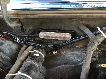
Step 3: Removing the ABS sensor
Sticking through the face of the spindle is a silver tube inside a metal block, which is the ABS sensor. In the next picture, you can see the bolts you have to remove, including that wacko 12-pt 6mm. Also remove the bolt at the top of the knuckle that secures the wiring to it.

Once you have removed the bolts, you can take off the block surrounding the sensor itself. In theory, now you should be able to push the sensor through the hole to remove it and then put it out of the way, but mine (and yours too, probably) is rusted and seized into the hole. If yours is like this, then go to Option #2
ABS Sensor Option #2 Using the BFH on it will destroy the sensor, so if it is stuck you will have to leave it in. Unclip the wiring clamp on the frame and unplug the connector that is up and attached to the radiator support. The sensor will stay as part of the knuckle, and be a pain in the ass the whole time. Its better than spending $60+ on a new one.
Step 4: Remove spindle and driveshaft
Remove the nuts around the perimeter of the spindle that hold it onto the knuckle. Then take the large rubber mallet and whack around the sides of the spindle, you might have to assist with the flathead screwdriver. Once it comes loose, pull the spindle off of the end of the axle.
Now if you are on the driver's side, you can just slide the axle out. Put your hand inside the radius arm and support the axle so it doesn't get dragged through the crap inside or damage the seal on the differential.

If you are on the passenger side, then you need to cut off the metal band on the slip joint boot, then you can do the same as on the driver's side and just pull the axle out. Hold onto the axle at the slip joint so it does not tear the boot when it separates from the slip joint and drops down.

Now put the driveshaft and spindle on the side for later, we will deal with rebuilding them after reinstalling the knuckle.
Step 5: Removing the knuckle
Remove the pinch bolt and snap ring from the upper ball joint. Then remove the cotter pin and nut from the lower ball joint. You will need a large breaker bar for this. Now you have to remove the bushing from the upper ball joint.
If you are reusing the same adjuster, then mark its position so you can put it back where it was. I used a air chisel to drive it out, but you could also use a hammer. Whatever method you use, just get it out.

Now for the fun part. Put something under the knuckle so when it pops loose it doesn't fall on your foot or the floor, turn the knuckle all the way for access to the lower ball joint stud, and smash the crap out of it with the BFH. Now is the time to be angry. It will suddenly pop loose and fall off, probably surprising you.

Go take a break, you probably need it by now...
Step 6: Pressing out the ball joints
You will need to use the C frame press for this step. Some people say to put the knuckle in a vise, but it was much easier for me to do it on the floor, so I could stand with one foot on the knuckle and one on the breaker bar. If you have someone to hold the cups and adapters while you tighten the press, its a lot easer to get it set up.
First remove the snap ring on the bottom, then you can take out the lower joint,

Then the upper, put a rag in the hole for the lower so the press doesn't mess it up.

Step 7: Clean up the knuckle
Before you start installing the new ball joints, now is a good time to clean up some of the rust in important areas. A die grinder with a wire brush is good for this. Clean the caliper slides and the pad slides, the mating surface for the spindle, and the areas around where the ball joints go. Just DO NOT do anything to the actual bores where the ball joints are installed, except for lightly rubbing off any surface rust with a scotch-brite pad.
Step 8: Install new ball joints (finally, putting something back together)
The instructions for the ball joints say to install the lower first, and so I did.... which prevented me from installing the upper ball joint. (and I had to take it back out again) If you are using the Harbor Freight press, you must install the upper one first, its the only way it works.
Press in the upper joint now

Then you can press in the lower joint and put on the snap ring

Step 9: Install knuckle
Hold the knuckle on and finger tighten the nut on the lower ball joint. Now take a jack and put it directly under the lower joint, make sure you have it turned all the way to one side so you can put the torque wrench in. Jack it up a little bit to put some pressure on the stud, this keeps the stud from spinning while it is tightened. Torque it to spec and install the cotter pin, if the holes do not align, tighten it more, do not loosen it.

Now either re-install the old camber bushing or install a new two-peice adjustable one. Put the snap ring on and install and tighten the pinch bolt just until the stud stops turning with the knuckle when you move it, then back off slightly so it moves again. You must torque it once the vehicle is back together and on the ground.
Step 10: Rebuild and install the driveshaft
You will need your vise and the press for this. Wrap a rag around the long part of the shaft and insert it in the vise. Take a screwdriver and a hammer and knock off the retaining clips that hold the u-joint in. If they are rusted to heck, use the wire brush on the die grinder to get rid of some of the rust. If you can only get one clip off, that's ok, you can press it first toward the side with the clip removed, and the stuck clip will then free up and can be removed.
When doing the pressing, I tightened up the press as hard as I could but the joint would not do anything. The trick is to whack it with a hammer while the press is tight. Wear safety glasses and hold onto the press in case it pops off. When it decides to pop, there will be a loud bang and rust flakes will fly everywhere.
Press the joint though, remove the cup, then push it back through the way it came and remove the second cup. Then it can be removed from the stub axle shaft.
First remove the joint from the longer part of the shaft

Then carefully put the short part into the vise (don't smash the bearing surface or the splines) and remove the joint from it.

Now take the wire brush on the die grinder and clean off as much rust as you can, but DO NOT touch the inside of the bores where the cups go. Just take a scotch-brite pad and clean off any surface rust.
Now reverse the removal process and install a new u-joint and c-clips.

Now you need to install a new seal on the end. Use a screwdriver and knock off the old seal, and clean any rust off of the step where the seal goes. I used a Timken kit, which comes with a metal plate and a new gasket. You must heat the plate on a stove until it glows red, then run out to the garage and toss it on, and whack it down. Don't burn yourself, I accidentally touched part of it and it melted right through my glove. (singed my finger)

Once it's cool, put the rubber part of the gasket on, and put some grease on the seal and the lower step of the shaft. Then reinstall it into the differential.
On the driver's side, just make sure the end is clean, and carefully slide it into the differential, don't stick it into any of the gunk on its way in.
On the passenger's side, clean and grease the splines, and then grease the inside of the slip joint. Slide it together, and replace the metal band with a zip tie or another metal ring if you have the tool to do so.

Step 11: Rebuild and reinstall the spindle
A note: The new rebuild kit I used had a different seal arrangement compared to the original, your truck / kit may be different, originally my truck had, in order, bearing - press in seal - plastic plate - small seal on driveshaft. The kit is bearing - rubber v shaped seal - plastic plate - large seal and metal plate on driveshaft.
Put the spindle in the vise with a rag on the 2nd step, remove the plastic piece and pry out the seal with a screwdriver. Then flip it over in the vise, clamp onto the ridge that is on the back (with the rag) and use a long rod or screwdriver and a hammer to pound out the spindle bearing. Push it out evenly by constantly switching which side you are hitting it on.
Clean up the spindle with brake parts cleaner and use the wire wheel on the die grinder to clean off rust and crud on the back part of the spindle, don't do anything to the machined surfaces.
Now take the new spindle bearing, pack it with grease, and use the seal installer, with the correct size driving plate to push the bearing in. Install the new seal, and then stick on the plastic plate with the bevel showing.

Step 12: Install the spindle
Put a coating of grease on the surfaces where the spindle meets the knuckle, then slip it on, and torque the nuts to spec.

Step 13: Close up the odds & ends
Reinstall the ABS sensor, the block that goes around the sensor, and the two bolts that hold it together. Then install the grease fittings and grease up all the new joints, pump em full until grease squeezes out or the boot begins to expand.
Reinstall the tie rod end, torque the castellated nut to spec, and install a new cotter pin. Install the dust shield with the three shorter bolts, then use the one longer one to reattach the abs wiring to the top of the spindle.
If you followed Option #2 for dealing with the ABS sensor, run the wiring back into the clamp and reconnect the plug.

Step 14: Install the wheel bearings, brakes, and hubs
Once again, refer to Glacier's brake tutorial for installing the rotors and calipers. Don't forget to clean the slides on the caliper and grease all of them. Install anti-rattle clips on the inner pad.

Step 15: Torque the pinch bolt <--- DON'T FORGET!!
Once you have the truck with the tires on and lowered to the ground, turn the tires slightly for clearance and use an extension to tighten the pinch bolt to spec. Having the right length extension makes a big difference, I didn't have one so I used a swivel, which you shouldn't when torquing anything, but it needed to be aligned so it was close enough for the ~3 mile trip to the shop.
Unless you put the adjusters back the way they were, and the truck was not aligned with the bad ball joints, then you will probably need a wheel alignment.
I'm open for recommendations on anything I can do to improve this tutorial, if you think I screwed up, missed anything, or forgot something let me know and I will fix it. Feedback is appreciated, and before anyone thanks me for doing this, I would like to thank everyone at EF for making this possible.
___________________________________________________________________
Copyright Ted Jarosinski - No part of this tutorial may be copied outside of Explorerforum without my permission. All photos taken with Canon Digital Rebel XTi, with 18-55 kit lens and Gary Fong Puffer flash diffuser. Editing done in Aperture.
This was done on a '94 Sport 4X4 w/ 4 Wheel ABS
___________________________________________________________________
Disclaimer: I cannot be responsible for any damage to you or your property that comes from following this guide. Use common sense and safety equipment (when necessary) to prevent injuring yourself or your truck. I cannot guarantee that this procedure is error-free. You have been warned.
Step 0: Preparation
You will need these specialty tools:
12pt, 6mm 1/4 Drive Socket (really hard to find, get out the phone book and start calling)
C-Frame Press (can be gotten from loan-a-tool or buy the Harbor Freight one)
Seal installer kit (you can make do without it, but its easier with it)
2-3/8in Wheel bearing locknut (with appropriate socket adapter if it has a huge drive size)
Snap ring pliers
You will also need: (not necessarily a complete list)
Jack and jackstands
Set of both metric and standard 1/2 drive sockets, impact is preferable
Set of both metric and standard 1/4 drive sockets
BFH of at least 2lb
Large rubber mallet
Smaller sized ball-peen hammer
1/2 Drive torque wrench
1/2 Drive breaker bar
1/2 Drive ratchet
1/4 Drive ratchet
1/4 Drive asstd. extensions
Set of small wrenches
Set of various picks
Flathead screwdriver (a crappy one for pounding/prying)
Vise
Kroil or PB Blaster
At least 2 cans of brake parts cleaner
Can of bearing grease
Box of latex gloves
Mechanic's Gloves
At least 2 rolls of paper towels
Shop rag
Scotch-brite pad
Grease gun
Air tools are optional but save a lot of work, I used:
Die grinder with wire brush
1/2 Impact
Air chisel with regular straight chisel
Parts I used:
Moog Ball joints
Timken bearings and spindle rebuild kit
U-Joints (I forget the brand, use spicer if you can)
Spicer Adjustable camber bushings
Valvoline Premium grease (in the black can)
Motorcraft pads and rotors
Step 1: Getting to the spindle
Since Glacier made such a great 1st gen brake tutorial, I don't see the reason for me to repeat him. Follow his instructions for getting the rotor off, then go to Step 2.
http://explorerforum.com/forums/showthread.php?t=122696
A big s-hook over the shock tower holds the caliper well and out of the way. If you have ABS, remove the sensor wire from the clips attaching it to the brake hose.
Step 1.5 Clean the Auto hubs
Yours may or may not be as bad as mine, but my auto hubs were seriously nasty when I took them off
FIrst they were soaked in stale gas, then I used a whole can of brake parts cleaner flushing gunk out of them. Then they were filled with ATF and left to sit for the remainder of the project. If yours aren't very bad, you can just soak them in ATF and skip the other steps. Drain off all of the goo into a jug, don't pour it on the ground. Once you get near the end, during the brake installation, dump them out and let them drip out, then they'll be ready to go once you're done with the brakes.
Step 2: Remove dust shield and tie rod end
Take the three screws holding the dust shield on out and remove the dust shield. Then, on the tie rod end, take out the cotter pin and loosen the castellated nut. Remove the nut until it is just past the end of the threads and smack it with the BFH. It should pop out of its taper and become free. Remove the nut, then use a peice of rope to tie it up to the sway bar to keep it out of the way. Now is also a good time to hose down everything you will be removing with penetrating oil.
Step 3: Removing the ABS sensor
Sticking through the face of the spindle is a silver tube inside a metal block, which is the ABS sensor. In the next picture, you can see the bolts you have to remove, including that wacko 12-pt 6mm. Also remove the bolt at the top of the knuckle that secures the wiring to it.
Once you have removed the bolts, you can take off the block surrounding the sensor itself. In theory, now you should be able to push the sensor through the hole to remove it and then put it out of the way, but mine (and yours too, probably) is rusted and seized into the hole. If yours is like this, then go to Option #2
ABS Sensor Option #2 Using the BFH on it will destroy the sensor, so if it is stuck you will have to leave it in. Unclip the wiring clamp on the frame and unplug the connector that is up and attached to the radiator support. The sensor will stay as part of the knuckle, and be a pain in the ass the whole time. Its better than spending $60+ on a new one.
Step 4: Remove spindle and driveshaft
Remove the nuts around the perimeter of the spindle that hold it onto the knuckle. Then take the large rubber mallet and whack around the sides of the spindle, you might have to assist with the flathead screwdriver. Once it comes loose, pull the spindle off of the end of the axle.
Now if you are on the driver's side, you can just slide the axle out. Put your hand inside the radius arm and support the axle so it doesn't get dragged through the crap inside or damage the seal on the differential.
If you are on the passenger side, then you need to cut off the metal band on the slip joint boot, then you can do the same as on the driver's side and just pull the axle out. Hold onto the axle at the slip joint so it does not tear the boot when it separates from the slip joint and drops down.
Now put the driveshaft and spindle on the side for later, we will deal with rebuilding them after reinstalling the knuckle.
Step 5: Removing the knuckle
Remove the pinch bolt and snap ring from the upper ball joint. Then remove the cotter pin and nut from the lower ball joint. You will need a large breaker bar for this. Now you have to remove the bushing from the upper ball joint.
If you are reusing the same adjuster, then mark its position so you can put it back where it was. I used a air chisel to drive it out, but you could also use a hammer. Whatever method you use, just get it out.
Now for the fun part. Put something under the knuckle so when it pops loose it doesn't fall on your foot or the floor, turn the knuckle all the way for access to the lower ball joint stud, and smash the crap out of it with the BFH.
Now is the time to be angry. It will suddenly pop loose and fall off, probably surprising you.Go take a break, you probably need it by now...
Step 6: Pressing out the ball joints
You will need to use the C frame press for this step. Some people say to put the knuckle in a vise, but it was much easier for me to do it on the floor, so I could stand with one foot on the knuckle and one on the breaker bar. If you have someone to hold the cups and adapters while you tighten the press, its a lot easer to get it set up.
First remove the snap ring on the bottom, then you can take out the lower joint,
Then the upper, put a rag in the hole for the lower so the press doesn't mess it up.
Step 7: Clean up the knuckle
Before you start installing the new ball joints, now is a good time to clean up some of the rust in important areas. A die grinder with a wire brush is good for this. Clean the caliper slides and the pad slides, the mating surface for the spindle, and the areas around where the ball joints go. Just DO NOT do anything to the actual bores where the ball joints are installed, except for lightly rubbing off any surface rust with a scotch-brite pad.
Step 8: Install new ball joints (finally, putting something back together)
The instructions for the ball joints say to install the lower first, and so I did.... which prevented me from installing the upper ball joint. (and I had to take it back out again) If you are using the Harbor Freight press, you must install the upper one first, its the only way it works.
Press in the upper joint now
Then you can press in the lower joint and put on the snap ring
Step 9: Install knuckle
Hold the knuckle on and finger tighten the nut on the lower ball joint. Now take a jack and put it directly under the lower joint, make sure you have it turned all the way to one side so you can put the torque wrench in. Jack it up a little bit to put some pressure on the stud, this keeps the stud from spinning while it is tightened. Torque it to spec and install the cotter pin, if the holes do not align, tighten it more, do not loosen it.
Now either re-install the old camber bushing or install a new two-peice adjustable one. Put the snap ring on and install and tighten the pinch bolt just until the stud stops turning with the knuckle when you move it, then back off slightly so it moves again. You must torque it once the vehicle is back together and on the ground.
Step 10: Rebuild and install the driveshaft
You will need your vise and the press for this. Wrap a rag around the long part of the shaft and insert it in the vise. Take a screwdriver and a hammer and knock off the retaining clips that hold the u-joint in. If they are rusted to heck, use the wire brush on the die grinder to get rid of some of the rust. If you can only get one clip off, that's ok, you can press it first toward the side with the clip removed, and the stuck clip will then free up and can be removed.
When doing the pressing, I tightened up the press as hard as I could but the joint would not do anything. The trick is to whack it with a hammer while the press is tight. Wear safety glasses and hold onto the press in case it pops off. When it decides to pop, there will be a loud bang and rust flakes will fly everywhere.
Press the joint though, remove the cup, then push it back through the way it came and remove the second cup. Then it can be removed from the stub axle shaft.
First remove the joint from the longer part of the shaft
Then carefully put the short part into the vise (don't smash the bearing surface or the splines) and remove the joint from it.
Now take the wire brush on the die grinder and clean off as much rust as you can, but DO NOT touch the inside of the bores where the cups go. Just take a scotch-brite pad and clean off any surface rust.
Now reverse the removal process and install a new u-joint and c-clips.
Now you need to install a new seal on the end. Use a screwdriver and knock off the old seal, and clean any rust off of the step where the seal goes. I used a Timken kit, which comes with a metal plate and a new gasket. You must heat the plate on a stove until it glows red, then run out to the garage and toss it on, and whack it down. Don't burn yourself, I accidentally touched part of it and it melted right through my glove. (singed my finger)
Once it's cool, put the rubber part of the gasket on, and put some grease on the seal and the lower step of the shaft. Then reinstall it into the differential.
On the driver's side, just make sure the end is clean, and carefully slide it into the differential, don't stick it into any of the gunk on its way in.
On the passenger's side, clean and grease the splines, and then grease the inside of the slip joint. Slide it together, and replace the metal band with a zip tie or another metal ring if you have the tool to do so.
Step 11: Rebuild and reinstall the spindle
A note: The new rebuild kit I used had a different seal arrangement compared to the original, your truck / kit may be different, originally my truck had, in order, bearing - press in seal - plastic plate - small seal on driveshaft. The kit is bearing - rubber v shaped seal - plastic plate - large seal and metal plate on driveshaft.
Put the spindle in the vise with a rag on the 2nd step, remove the plastic piece and pry out the seal with a screwdriver. Then flip it over in the vise, clamp onto the ridge that is on the back (with the rag) and use a long rod or screwdriver and a hammer to pound out the spindle bearing. Push it out evenly by constantly switching which side you are hitting it on.
Clean up the spindle with brake parts cleaner and use the wire wheel on the die grinder to clean off rust and crud on the back part of the spindle, don't do anything to the machined surfaces.
Now take the new spindle bearing, pack it with grease, and use the seal installer, with the correct size driving plate to push the bearing in. Install the new seal, and then stick on the plastic plate with the bevel showing.
Step 12: Install the spindle
Put a coating of grease on the surfaces where the spindle meets the knuckle, then slip it on, and torque the nuts to spec.
Step 13: Close up the odds & ends
Reinstall the ABS sensor, the block that goes around the sensor, and the two bolts that hold it together. Then install the grease fittings and grease up all the new joints, pump em full until grease squeezes out or the boot begins to expand.
Reinstall the tie rod end, torque the castellated nut to spec, and install a new cotter pin. Install the dust shield with the three shorter bolts, then use the one longer one to reattach the abs wiring to the top of the spindle.
If you followed Option #2 for dealing with the ABS sensor, run the wiring back into the clamp and reconnect the plug.
Step 14: Install the wheel bearings, brakes, and hubs
Once again, refer to Glacier's brake tutorial for installing the rotors and calipers. Don't forget to clean the slides on the caliper and grease all of them. Install anti-rattle clips on the inner pad.
Step 15: Torque the pinch bolt <--- DON'T FORGET!!
Once you have the truck with the tires on and lowered to the ground, turn the tires slightly for clearance and use an extension to tighten the pinch bolt to spec. Having the right length extension makes a big difference, I didn't have one so I used a swivel, which you shouldn't when torquing anything, but it needed to be aligned so it was close enough for the ~3 mile trip to the shop.
Unless you put the adjusters back the way they were, and the truck was not aligned with the bad ball joints, then you will probably need a wheel alignment.
I'm open for recommendations on anything I can do to improve this tutorial, if you think I screwed up, missed anything, or forgot something let me know and I will fix it. Feedback is appreciated, and before anyone thanks me for doing this, I would like to thank everyone at EF for making this possible.
___________________________________________________________________
Copyright Ted Jarosinski - No part of this tutorial may be copied outside of Explorerforum without my permission. All photos taken with Canon Digital Rebel XTi, with 18-55 kit lens and Gary Fong Puffer flash diffuser. Editing done in Aperture.