So let me first start with a quick introduction .. my name is Barack Obama and apparently I'm the junior US Senator from Illinois  . I love slow walks on the beach and bed-side stories. Yeah I'm talking to you big boy:

Okay now onto the goods...
So recently I've been starting a few threads all relating to my Dana 44 front axle and other tid bits - so I figured it would be best if I just started an SAS thread to pull all of those threads together into one centralize place instead of having them floating about the sea of other threads.
Follow me now as I look back on the threads that I've started:
1) Reading Pinion Depth Number In this thread, I was confused on which number was the pinion depth offset number of my ring and pinion set for the Dana 44. After calling up the good people of Randy's Ring and Pinion, I was told that the numbers on the ring and pinion are no longer used for the pinion depth offset. So I'm like wtf m8!? They did give me a number to start from and so thats what I started with.
2) Ford 9" For Off-Road Use In this thread, I ask the general public what they think about the Ford-9" axle for off-road use. Conclusion, bowties - the GM 14-bolt axle with the stock Detroit locker is a God's send and so thats what I'm going with (it comes with a pinion bearing support - just like the Ford-9").
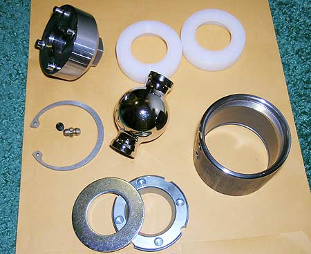
3) RE SuperFlex Assemby I've never put together a Rubicon Express SuperFlex Joint so in this thread, I ask the public how in the world these things are put togehter. And to be more specific, I was confused how to drive the plastic bushings into the housing. Conclusion - use a press <- faaantastic.
4) Hi-Steer Arms 10-degree Correction In this fabulous discussion, we discuss the ever-popular 10-degree correction that is often placed on High-Steer Arms. In the end, I decided to go with the Sky-Manufacturing arms (although I never updated the thread I dont think - darnit).
5) Dana 44 Ball Joint Sleeve > Replace? Ah finally, the pain in the asymptote. In this thread, which I have yet to resolve really, the problem is that the upper Ball Joint sleeve has frozen itself onto the "C" (aka inner knuckle). The issue has yet to be resolved so no conclusion yet.
Well then, lets dive into some concepts and design ideas.
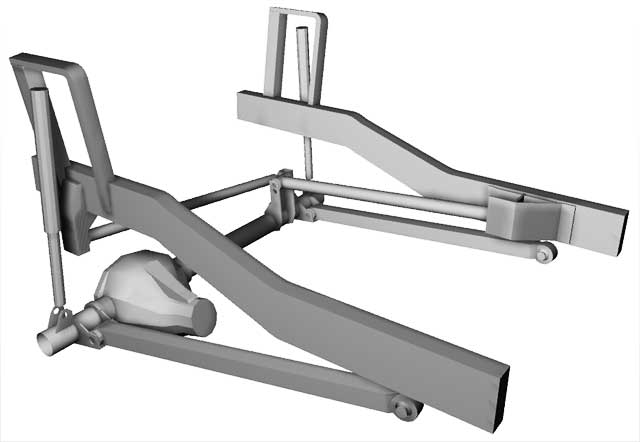
As you can see, the front axle is located via a 3-link with a panhard bar. Each link will be mounted to the chassis using Rubicon Express Large SuperFlex Joint. Why go with the RE Joint? Well I was quite impressed at how much JEFE's front axle flexed - so I decided to go with the same joint. I recently asked him whether or not he has broken the 9/16" bolts used to attach the joint to the chassis and he said no - a big . The link's body is made of a 2"x2" - 0.25" wall square tube - similar to Clayton Off-Road's long arms. Currently, my calculations are aiming for the bottom links to be 38.7" in length and the upper to be 34.2" (figures may change). This gives me an anti-dive of about 105% but I will make the upper link adjustable vertically at the chassis so the anti-dive characteristic can be fine tuned. The bottom links are angled "toe-out" becaue the Dana 44 is a "Wide-Track" axle and the Explorer's chassis is about 2" narrower than the Wide-Track axle's ideal mounting points. The "toe-out" angle however is not severe : about 2" out for the about total 38" length. The two bottom links are attached to the axle via a regular rubber-bushing. The upper "third" link is attached to the axle with the same type of rubber bushing except this one is adjustable - to allow for pinion angle changes.
Onto the front axle itself: As stated, the front "Wide Track" axle is from a Grand Wagoneer (I believe '86). Currently, its geared 5.13 with open differential. I'll throw in a locker in the future after I get this running. The axle was originally running the Wagoneer 6-lug bolt pattern but, because the rear GM 14-bolt is 8-lug, I switched the Dana 44 to 8-lug pattern using parts from a K20 (caliper bracket from a J20). As for the high-steer arms, as stated previously, I decided to go with SkyManufacturing's standard arms with the 10-degree correction angle (arms are on their way from CA).
The steering gear box is out of an IFS Toyota and the entire steering setup will utilize only Chevy TRE's except at the pitman arm.
The front axle will be suspended by Fox 2.5" Nitrogen Air Shocks with 16" of travel.
The rear axle, again as stated before, is a GM 14-bolt with a Detroit locker. Initially, it will be leaf sprung using the Explorer's stock leaf springs (with an AAL and WAR153s). However, I do plan on going 4-link in the near future after the Explorer starts rolling again.
Now onto some newbie pics..
The axle the day it arrived from New Jersey:
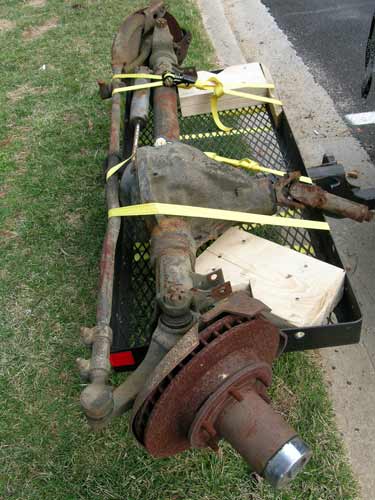
Before last winter came, I emptied an entire can of Liquid Wrench (and other llubricants) into the differential to soak everything down in preparation for the following spring.
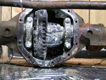
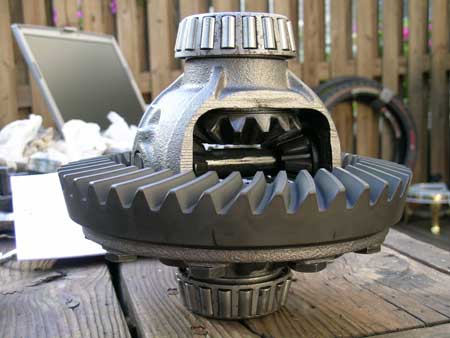
When spring finally came, the axle was torn down:
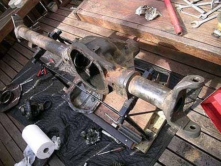
New carrier and new gears. The carrier bearings below are the set-up bearings which have had their inner races grinded down for repetative installation and removal on the carrier while the pinion and ring gear geometry was fine tuned:
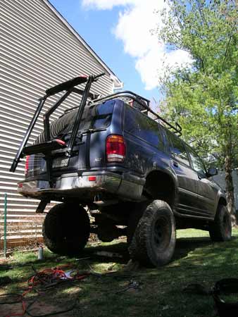
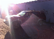
Spring also brought wheeling weather and I got high-centered on a rock so I decided to SOA the back for fun (the thing on the back is my snowboard and bike rack) and had to get my driveshaft retubed because it popped in half:
The caliper brakets from a J20 after sand blasting and a coat of epoxy paint:
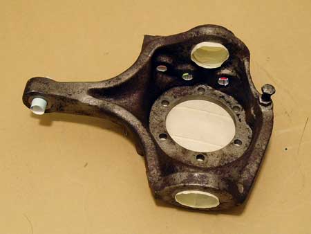
Flat-top knuckles from a J10 masked off and ready for some epoxy paint:
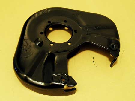
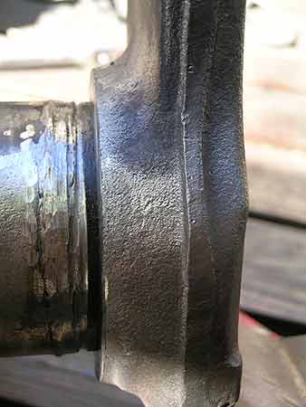
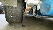
Inner "C"s on the front axle sliced from the axle tubes (and temporarily knocked out about .125" for easier rotation) to set proper caster angle:
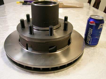
Chevy K20 8-lug rotors .. "Oh my Mr. Obama, what big rotors you have. Why yes Sally, I do have big rotors." :
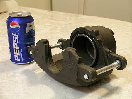
Chevy K20 calipers:
And finally for now, the RE SuperFlex joints:
As for tires, right now I have a set of 36" TSL-SX's I bought for cheap from a local individual.
So what's in the future? Well the rest of the link parts are on their way - as well as the high steer arms. The Fox shocks will be purchased in about 2 weeks and the 14-bolt axle will be picked up about 3 weeks to a month after that. The rear axle is the least of my worries so that's the last thing on this Senator's mind.
. I love slow walks on the beach and bed-side stories. Yeah I'm talking to you big boy:
Okay now onto the goods...
So recently I've been starting a few threads all relating to my Dana 44 front axle and other tid bits - so I figured it would be best if I just started an SAS thread to pull all of those threads together into one centralize place instead of having them floating about the sea of other threads.
Follow me now as I look back on the threads that I've started:
1) Reading Pinion Depth Number In this thread, I was confused on which number was the pinion depth offset number of my ring and pinion set for the Dana 44. After calling up the good people of Randy's Ring and Pinion, I was told that the numbers on the ring and pinion are no longer used for the pinion depth offset. So I'm like wtf m8!? They did give me a number to start from and so thats what I started with.
2) Ford 9" For Off-Road Use In this thread, I ask the general public what they think about the Ford-9" axle for off-road use. Conclusion, bowties - the GM 14-bolt axle with the stock Detroit locker is a God's send and so thats what I'm going with (it comes with a pinion bearing support - just like the Ford-9").
3) RE SuperFlex Assemby I've never put together a Rubicon Express SuperFlex Joint so in this thread, I ask the public how in the world these things are put togehter. And to be more specific, I was confused how to drive the plastic bushings into the housing. Conclusion - use a press <- faaantastic.
4) Hi-Steer Arms 10-degree Correction In this fabulous discussion, we discuss the ever-popular 10-degree correction that is often placed on High-Steer Arms. In the end, I decided to go with the Sky-Manufacturing arms (although I never updated the thread I dont think - darnit).
5) Dana 44 Ball Joint Sleeve > Replace? Ah finally, the pain in the asymptote. In this thread, which I have yet to resolve really, the problem is that the upper Ball Joint sleeve has frozen itself onto the "C" (aka inner knuckle). The issue has yet to be resolved so no conclusion yet.
Well then, lets dive into some concepts and design ideas.
As you can see, the front axle is located via a 3-link with a panhard bar. Each link will be mounted to the chassis using Rubicon Express Large SuperFlex Joint. Why go with the RE Joint? Well I was quite impressed at how much JEFE's front axle flexed - so I decided to go with the same joint. I recently asked him whether or not he has broken the 9/16" bolts used to attach the joint to the chassis and he said no - a big
. The link's body is made of a 2"x2" - 0.25" wall square tube - similar to Clayton Off-Road's long arms. Currently, my calculations are aiming for the bottom links to be 38.7" in length and the upper to be 34.2" (figures may change). This gives me an anti-dive of about 105% but I will make the upper link adjustable vertically at the chassis so the anti-dive characteristic can be fine tuned. The bottom links are angled "toe-out" becaue the Dana 44 is a "Wide-Track" axle and the Explorer's chassis is about 2" narrower than the Wide-Track axle's ideal mounting points. The "toe-out" angle however is not severe : about 2" out for the about total 38" length. The two bottom links are attached to the axle via a regular rubber-bushing. The upper "third" link is attached to the axle with the same type of rubber bushing except this one is adjustable - to allow for pinion angle changes.Onto the front axle itself: As stated, the front "Wide Track" axle is from a Grand Wagoneer (I believe '86). Currently, its geared 5.13 with open differential. I'll throw in a locker in the future after I get this running. The axle was originally running the Wagoneer 6-lug bolt pattern but, because the rear GM 14-bolt is 8-lug, I switched the Dana 44 to 8-lug pattern using parts from a K20 (caliper bracket from a J20). As for the high-steer arms, as stated previously, I decided to go with SkyManufacturing's standard arms with the 10-degree correction angle (arms are on their way from CA).
The steering gear box is out of an IFS Toyota and the entire steering setup will utilize only Chevy TRE's except at the pitman arm.
The front axle will be suspended by Fox 2.5" Nitrogen Air Shocks with 16" of travel.
The rear axle, again as stated before, is a GM 14-bolt with a Detroit locker. Initially, it will be leaf sprung using the Explorer's stock leaf springs (with an AAL and WAR153s). However, I do plan on going 4-link in the near future after the Explorer starts rolling again.
Now onto some newbie pics..
The axle the day it arrived from New Jersey:
Before last winter came, I emptied an entire can of Liquid Wrench (and other llubricants) into the differential to soak everything down in preparation for the following spring.
When spring finally came, the axle was torn down:
New carrier and new gears. The carrier bearings below are the set-up bearings which have had their inner races grinded down for repetative installation and removal on the carrier while the pinion and ring gear geometry was fine tuned:
Spring also brought wheeling weather and I got high-centered on a rock so I decided to SOA the back for fun (the thing on the back is my snowboard and bike rack) and had to get my driveshaft retubed because it popped in half:
The caliper brakets from a J20 after sand blasting and a coat of epoxy paint:
Flat-top knuckles from a J10 masked off and ready for some epoxy paint:
Inner "C"s on the front axle sliced from the axle tubes (and temporarily knocked out about .125" for easier rotation) to set proper caster angle:
Chevy K20 8-lug rotors .. "Oh my Mr. Obama, what big rotors you have. Why yes Sally, I do have big rotors." :
Chevy K20 calipers:
And finally for now, the RE SuperFlex joints:
As for tires, right now I have a set of 36" TSL-SX's I bought for cheap from a local individual.
So what's in the future? Well the rest of the link parts are on their way - as well as the high steer arms. The Fox shocks will be purchased in about 2 weeks and the 14-bolt axle will be picked up about 3 weeks to a month after that. The rear axle is the least of my worries so that's the last thing on this Senator's mind.
 . One downside to air shocks is their spring rate curve is totally different from coils, leaf springs, or coil-overs (tho coil-overs can be setup to mimic air shocks). It has horrible ant-sway characteristics because the "bottom" end of the spring rate curve maintains a constant rate for quite a bit instead of being more quadriatic which is traditional of leaves, coils, and coil-overs. But I think this is a plus on the trails


