x5050160
Active Member
- Joined
- May 20, 2013
- Messages
- 79
- Reaction score
- 0
- City, State
- Saint Joseph
- Year, Model & Trim Level
- 1994 Explorer XLT
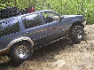
My Radius Arm bushings are shot all to hell. No matter what way you go about it the job looks as though it is a *****. Plus my RA brackets have lost the factory protective coating and have some surface rust on them now. If I am going to do this job I'm doing all of it at once. Factory parts lasted 20 plus years. I wanna upgrade. I do not want to lift the X. Keep in mind this is all theroy as I have not had any of this apart before and Im going off of just looking at my X up on the lift and the pictures in diggity0169's write up.
How to: Ford Explorer - Ranger Radius Arm Bushing Repair
So I am thinking of doing a mod to my radius arm and radius arm bracket. I want to get rid of the "Radius Arm" type set up. Green arrows Pictures are not from any Ford Explorer.

I want to do a control arm set up. Like this kinda: Green arrows once again.

I do want to utilize the stock Radius Arm to Traction Beam setup. I do not want to shorten or lengthen the radius arm except for the necessary amount to account for the placement of the "control arm" bracket. This modification would basically serve the purpose of an ease of maintenance and strength upgrade.
My thoughts on the control arm bracket are to cut and weld it out of 3/16th's A-36 steel plate. Use the existing holes in the frame to bolt it up. I am thinking of using 2x4x.188 rectangular tubing for the fab of the cross member to connect the two brackets. I would mock it up so the pivot angle would match the angle of the factory RA bushing.
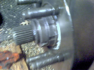
My thoughts on the Radius Arm is to leave it stock except to use .188" wall tubing to replace the stub end and then use 1" OD x .760 ID x .120 Wall 304 Stainless for the control arm eyelet. I don't really know what size tubing is going to work for the mod to the stub end of the CA. I would also like to gusset the end of the arm towards the TTB end of it.
Now I do have a few concerns
The first being losing the 360° motion that the radius arm allows. I am just assuming here, but I would guess that there is 360°'s of motion due to there being rubber bushing all around the RA stub. Thus allowing some lateral movement of the TTB???? If I were to go with a control arm like set up I figure I would be greatly limiting this movement. There would only be a very small amount of crush with the bushing in the control arm eyelet.
The second being the strength of the frame at the bracket location. A control arm as stated above should have a lot less "give" thereby exerting greater force on the bracket, cross member, and the frame.
Should I think of using bigger stainless tubing for the eyelet to allow for a thicker bushing? What if I were to box the frame around the location of the bracket? Can I even do that.
If you all have any ideas on this let me know. Any input at all would be great. I got awhile before I get to do this. (It'll be winter when the project starts)
How to: Ford Explorer - Ranger Radius Arm Bushing Repair
So I am thinking of doing a mod to my radius arm and radius arm bracket. I want to get rid of the "Radius Arm" type set up. Green arrows Pictures are not from any Ford Explorer.
I want to do a control arm set up. Like this kinda: Green arrows once again.
I do want to utilize the stock Radius Arm to Traction Beam setup. I do not want to shorten or lengthen the radius arm except for the necessary amount to account for the placement of the "control arm" bracket. This modification would basically serve the purpose of an ease of maintenance and strength upgrade.
My thoughts on the control arm bracket are to cut and weld it out of 3/16th's A-36 steel plate. Use the existing holes in the frame to bolt it up. I am thinking of using 2x4x.188 rectangular tubing for the fab of the cross member to connect the two brackets. I would mock it up so the pivot angle would match the angle of the factory RA bushing.
My thoughts on the Radius Arm is to leave it stock except to use .188" wall tubing to replace the stub end and then use 1" OD x .760 ID x .120 Wall 304 Stainless for the control arm eyelet. I don't really know what size tubing is going to work for the mod to the stub end of the CA. I would also like to gusset the end of the arm towards the TTB end of it.
Now I do have a few concerns
The first being losing the 360° motion that the radius arm allows. I am just assuming here, but I would guess that there is 360°'s of motion due to there being rubber bushing all around the RA stub. Thus allowing some lateral movement of the TTB???? If I were to go with a control arm like set up I figure I would be greatly limiting this movement. There would only be a very small amount of crush with the bushing in the control arm eyelet.
The second being the strength of the frame at the bracket location. A control arm as stated above should have a lot less "give" thereby exerting greater force on the bracket, cross member, and the frame.
Should I think of using bigger stainless tubing for the eyelet to allow for a thicker bushing? What if I were to box the frame around the location of the bracket? Can I even do that.
If you all have any ideas on this let me know. Any input at all would be great. I got awhile before I get to do this. (It'll be winter when the project starts)