Yeah, the 04 is drive by wire type. Found this intresting article that basically disects the whole thing potato head style.
http://articles.d-tips.com/art8.html
Ford Electronic Throttle Control
By Glen Beanard technical contributor
What was wrong with a cable?
As if a simple cable linking the gas pedal to the throttle plate wasn’t good enough, engineers have now made that design complicated too. Why do engineers do these things to us? That expensive throttle body can’t cost less than a cheap little throttle cable; or can it? Are there any advantages to the manufacturer or the consumer with such a design? Let’s examine the system and see.
In the Ford ETC system, the PCM directly controls the position of the throttle plate by use of a DC motor. A redesigned throttle body, coupled with a redesigned PCM, a redesigned throttle position sensor (has 2 position sensors inside of it), and the addition of an accelerator pedal position sensor (APPS) make up the ETC system directly. The ETC system replaces the throttle cable and brackets, IAC valve and it’s wiring, cruise control servo, plus some wiring for the cruise system as well. The only part of the ETC system that is truly new (excluding redesigning) to the gasoline vehicle is the APPS, and it has been in service on the DI diesel for years. So with that considered, what appears to be more complicated on the surface, is actually less elaborate when viewing the entire scope. It might cost less to build too.
The principle reason for using the ETC system is for improved drivability through its torque based strategies, which take better advantage of VCT and transmission shift strategies. There are however, other benefits. It allows the PCM to limit vehicle speed and engine rev through throttle control, rather than inducing misfires. Also, adding factory cruise control to a vehicle that wasn’t originally equipped with cruise becomes a snap; Simply replace the steering wheel (in some cases replace the clock spring too) and “tell” the PCM it has cruise, with a capable scan tool. Nice huh?
The ETC system also helps pave the way for future design changes to the vehicle’s passenger compartment as well; such as the consumer being able to slide the vehicle controls to the opposite side of the dash. ETC also makes it possible for the traditional throttle pedal to be eliminated all together by replacing it with hand controls on the steering wheel. That feature holds obvious potential for dealer or factory equipped handicap driver applications.
Now that we have talked about the names of the parts, let’s see how they operate.
Ford ETC Theory and Operation
Based on the APPS input, the PCM changes the angle of the throttle plate by directly actuating the DC motor mounted to the throttle body assembly. The TPS, mounted on the throttle body, provides feedback to the PCM of the throttle plate position. The purpose of the TPS has been modified in the ETC system from that of the cable type system. Rather than being the source of driver throttle demand information, the TPS is now simply for the PCM to be able to monitor its own actions with the throttle plate. The APPS sensor is now what represents the driver’s throttle demand. Which is something to keep in mind when reviewing fault code freeze frame data.
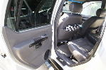
The APPS
(Photo #1)
(Figure #1)
The Accelerator Pedal Position Sensor (APPS) mounts to the top of the throttle pedal (photo #1). Inside of it are three position sensors and two return springs. The position sensors send an analog DC signal to the PCM, as you can see in figure #1.
The PCM uses APPS1 as the primary indicator of the driver’s throttle demand. APPS1 uses a negative slope. In the at-rest position, APPS1’s voltage is high, usually starting around 4.0 volts. As the pedal is depressed, the voltage lowers. With the pedal fully depressed, the voltage value will typically read just under 1.5volts. APPS2 is used to cross-check APPS1 against. The positive slope of APPS2 provides a more traditional position sensor behavior when viewed on a scanner. The voltage readings of APPS2 starts low in the rested position, and rises as the pedal is depressed. In the event that APPS1 were to fail, the PCM then looks at APPS2 as the source of driver demand information. If APPS1 and 2 don’t agree, APPS3 is then used to cross check APPS1 and APPS2 against. The two return springs inside the unit, help ensure the pedal will fully return in the event one should break or weaken. Trouble codes P2122, P2123, P2127, P2128, P2132, and P2133 are APPS sensor circuit continuity tests. Those codes all point to an open or short in the APPS circuits. Codes P2121, P2126, and P2131 are all related to the APPS performance or range. These codes are set when the PCM “sees” a signal from one of the 3 APPS that is present and active, but is not in the specified range. Codes P2138, P2140, and P2139 are APPS correlation codes. These are set when the PCM “sees” a discrepancy between 2 or more APPS readings. All of these codes will set a ETC lamp (wrench light or failsafe message), but not a MIL light (check engine light). These circuits are monitored continuously. The PCM will indicate any one of these faults within one second from the start of the condition.
The ETC Throttle Body Assembly
The electronic throttle body (ETB) is very similar to the cable operated throttle body, with a few notable changes. Among the most noticeable of changes, is the addition of the throttle actuator control motor (TAC). The motor is used to open and close the throttle plate based on direct command from the PCM. On Ford products, the motor is currently located either on the side of the throttle body or underneath, depending on application. There are only 2 wires to the motor. As you can see in photo #4, rather than simply bolting the motor to the side of a traditional throttle body, the throttle body is specially molded for mating with the motor. The TAC motor turns two reduction gears inside of the throttle body that link the drive gear from the motor to the throttle plate shaft. Although the motor can be removed from the throttle housing, it is not currently considered to be serviceable separate from the throttle body. Another change to the throttle body is the absence of the IAC motor and the tiny drilled hole in the throttle plate. This is because idle speed is controlled completely by throttle plate angle in this system. The throttle body has two springs inside of it. One is for throttle plate return, and the other is a “limp home” spring. The limp home spring is set to open the throttle about 8 degrees if the power to the DC motor is lost. This will result in an air flow equal to a high idle and will produce about 30mph constant speed. However, idle RPM will not be high because the PCM will induce misfire to lower the RPMs at idle.
One thing that does remain, is Ford’s age old warning not to clean the throttle body do to the presence of a coating that could be damaged by the cleaner. However, since the throttle plate is capable of supplying a much larger quantity of air than any IAC valve ever could, this system will not be effected by carbon in the throttle bore in the same manner as a cable operated throttle body.
The TPS
(Figure #2)
The TPS has been redesigned for ETC. The sensor is now actually two sensors inside of one housing; TPS1 and TPS2. TPS1 is viewed by the PCM as the primary source of throttle plate position under normal conditions. Notice in figure #2, TPS1 behaves in reverse to the traditional TPS, it has a negative slope. In the at-rest position, the voltage is near the 5 volt reference voltage. As the throttle plate opens, the voltage from TPS1 lowers. TPS2 is used to cross check TPS1 against. It is also looked at by the PCM for small throttle angle changes, because it has better resolution than TPS1. In the event that TPS1 fails, TPS2 becomes the PCM’s primary source of throttle plate position. The voltage from TPS2 behaves in the traditional manner. In the at-rest position, the voltage is less than 1 volt and raises toward reference voltage as the throttle plate opens.
TPS1 and 2 do not mimic each other in voltage value. As you can see, the slope angle of TPS2 is about twice that of TPS1. TPS1 provides a signal that covers the entire sweep much the same as the older version TPS on the cable operated system. The only real difference is that it is a negative slope. TPS2, however, reaches its peak voltage twice as fast. The voltage slopes change at different rates to further isolate TPS1 from TPS2 in the PCM’s “eyes”.
As you can see in photo #2, there are 4 wires going to the TPS. There is one 5 volt reference, 2 signal wires, and one common sensor ground.
Trouble codes P0122, P0123, P0222, and P223 all deal with TPS circuit continuity problems such as shorted or open circuits. These will set the ETC warning indicator and the MIL lamp both simultaneously. P0121 and P0221 indicate range and performance problems, such as one of the TPS readings being present, but out of spec. They will set only the ETC warning indicator. Code P2135 points to a correlation problem between the 2 TPS readings. This code will only illuminate the ETC indicator as well. The TP monitor is also continuous and will set a fault in less than 1 second from the start of the fault.
The Black Oak Power PC
The PCM has received an upgrade and a new name; the Black Oak Power PC (photo #3). The Black Oak Power PC is designed to run an ETC system and has some extra computing speed and processors, some new diagnostic codes, and some new strategies inside and out. Refer to the ETC functional diagram.
Inside the PCM is an E-Quizzer. The E-Quizzer acts as a watchdog inside the PCM. Its main job is to monitor the IPC and the main processor. It also monitors the APPS sensors at idle, compares them to the TPS at idle, and uses this information to “decide” if the PCM is making the right “decisions”. The E-Quizzer can deny fuel and ignition if it “sees” an unexpected value.
Another addition to the PCM is a throttle plate position controller (TPPC). It’s job is to control the actual throttle plate position so that it matches the desired position.
The TPPC monitors the TPS1 and TPS2 and controls the TAC via the H-bridge. The throttle plate position monitor runs continuously, and can set a fault in less than five seconds from the start of the fault.
The H-bridge, also called the H-driver, is the driver portion of the PCM for the TAC. It is capable of sending a positive and negative polarity voltage to the TAC.
The PCM has an independent plausibility check (IPC) that inspects powertrain torque and compares it against the driver’s demand. The IPC is a self examining software that helps to determine the health of the ETC system anytime the engine is running, and is the primary monitoring function which is on the main processor.
Rev, vehicle speed, and torque limiting are not new PCM strategies. However, the way that ETC PCM achieves these things are. The PCM now has it’s “choice” of how to control engine rpm. The PCM’s first “choice” is to limit RPMS and vehicle speed by the throttle plate position. This produces a smooth feeling in engine limitation. This may also produce a new description to an old customer complaint. If the PCM “sees” wheel slip on traction control equipped vehicle, over rev, or over speed, the customer will likely not notice a “skip”. Instead, they will notice a momentary vehicle slow-down, or the engine not increasing speed with the pedal, or a “flat spot“ in the throttle. In the event of a malfunction that hinders the PCM’s ability to control the throttle plate position, the PCM still uses ignition and fuel to induce a misfire, or even total engine shut down as a 2nd and 3rd option respectively.
There are some fault codes for the ETC system that only point to a strategic mode that the PCM entered. In all failure modes, the “wrench” light, or “engine failsafe mode” message will be displayed. In most cases, the “check engine” light will also be illuminated.
DTC P2104 - Forced Idle Mode
In this mode, the throttle plate is limited to idle speed and limited vehicle speed (about 30mph) only. This can be caused by 2 or more APPS sensor failures or a stuck throttle related DTC.
DTC P2105 - Forced Engine Shutdown
In this mode, the fuel injectors and fuel pump are shut off. This can be caused by internal PCM problems such as RAM, ROM, or E-quizzer faults.
DTC P2106 - Forced Limited Power
In this mode, some customers, may not notice a difference in running, depending on their driving habits. However, a difference will exist. The engine power will be limited to less than maximum. There will be no cruise control. Also, the engine RPMs will be limited, but can still be increased by pressing throttle pedal further. This can be caused by one throttle position sensor out of range or two that disagree with each other. A mass air flow, output shaft speed, or crank position sensor out of range can cause this, as well as a failed turbine speed sensor. If the actual engine torque exceeds the demanded torque, or if there is an E-quizzer or PCM failure after power up this mode will be set. This can also happen if the ETB motor circuit has high resistance, or if the throttle plate doesn’t fully return to an idle position when the throttle pedal is at the idle position.
DTC P2110 - Forced Limited RPM Mode
The throttle plate will be set to an idle RPM, however, if the ETB motor has power, then the engine RPMs can be raised by pressing the accelerator pedal. The cruise control will also be disabled. This failure mode can be caused by 2 throttle position sensors out of range. An improperly wired ETB motor or TPS can set this mode, as well as a stuck throttle plate. If the TPPC looses control of the throttle plate, or “thinks” it did for any of the mentioned external reasons, or for an internal PCM reason, this mode will be entered.
DTC P2110 and P2104 set together - Forced Limited RPM and Forced Idle Mode
With or without power to the ETB motor, the throttle plate will be forced to an idle position. As a result, the vehicle speed will be limited to a low fixed speed. Naturally, the cruise control will be inoperative as the throttle control will be base on a zero throttle position. This can be caused by TPPC failure, two TPS failures, or two or more APPS failures. Also, the PCM can experience internal faults such as E-quizzer and communications faults to set this mode. Should the ETB or TPS be improperly wired, the PCM will enter this mode as well.
No Effect on Drivability mode
This mode may be entered if only one APPS sensor fails, or if there is a PCM software problem.
Diagnostic Notes
(Photo #8)
(Photo #9)
(Photo #10)
As you can see, a code 2106 doesn’t automatically mean that the fault exists in a dedicated ETC component. In photo #10, you can see that this ‘05 Expedition has set a 2106. Check engine light illuminated and “Engine Failsafe Mode” message was displayed on the message center (photo #8). What set the 2106? Notice the MAF code and the IAT code. Looking at photo #9, we see that the mass air flow sensor had been found by the PCM to be out of range at the time the code was set. Since the ECT system is torque based and MAF sensor is required for the PCM to calculate torque, the disconnected MAF didn‘t just set MAF and IAT codes, but it also sent the PCM in to an ETC failsafe mode, code P2106.
(Photo #5)
(Photo #7)
(Photo #11)
In another instance, an F150 came in with a forced idle and limited RPM condition. The wrench light was illuminated. The engine was not responsive at all to the throttle pedal. The throttle plate was defaulted to the 8 degree setting. When the vehicle was not in motion, the PCM would induce a misfire to bring the RPMs down to idle speed. Then, when in motion, the PCM would stop inducing the misfire to provide a high-idle condition which would provide a top speed of around 30mph. Codes P2110 and P2104 were both set (see ETC photo #5). According to the description and operation, and considering the most likely, the suspects are APPS, TPS, and internal PCM faults. When scanning the APPS and TPS, both PIDs were normal and resembled the examples shown earlier in figures 1 and 2. The wiring was then checked between the TAC and the PCM as a precaution by unplugging the lead to the TAC and measuring at the open ended harness pigtail. This quick test shows that at least the wires are not open (photo #7). This voltage is normal to be found on both leads to TAC with key on, engine off. The cause of the truck’s lack of throttle is found in that funny looking code back in photo #5. The code P060B is part of a newer line of trouble codes that will be more common in the coming years. P060B is for “Internal control module analog to digital processing performance” see photo #11. Simply put, the PCM recognized a fault within its analog to digital converter. That P060B is part of a new line of codes that will continue to grow as time goes on. Another of these is P060X for “internal processor failure”. As you can see, the little letter at the end of the new codes does make a significant difference, because a P060 is a completely unrelated description of “HO2S Heater Resistance (Bank 2, Sensor 2)”.
The ETC system is popping up in vehicles everywhere, Volvo, Volkswagen, Isuzu, Gm, Chrysler, etc. The description and operation of these systems are very similar, but not perfectly identical. Be sure to always consult you information source for each make and model that you are servicing. Never assume just because it is similar, that it is the same.