This is a general how-to thread for fixing the transfer case shift motor for the 4X4 models. Many posts on this site have been great sources of information, but pictures are worth thousands of words. I wanted to put something up for people to point others to when they have 4X4 problems. So here am going to list some key words to help the searchers:
Transfer Case Electric Shift Motor 4X4 4x4 4WD 4wd 4X Borg Warner 13-54 BW1354 BW13-54
First thing is where is that 4X4 shift motor? You have to crawl underneath and look at the back of the transfer case (which is behind the transmission). Looking at it from behind it will look something like this:
It has been said that tapping or hitting the shift motor will sometimes get it to engage if it is stuck in a position. This may work (it's probably worth a try), but don'tt hit it too hard or you might be looking at $300 to get a replacement.
To straight out replace the motor with an OEM or aftermarket one, eight bolts are all that is needed to remove the motor. Four bolts hold on the weight that is used as a vibration dampener (not shown, but locations are marked in blue), and four bolts hold on the shift motor (locations marked in red are 10mm). Two of these bolts attach a bracket that secures the electrical connector as well as holding a sensor in place (it has an o-ring and just needs to be kept from popping out of the case). There is silicone sealant used between the shift motor and the t-case body, so a little gentle prying might be in order (and don'tt forget to seal it back up and make it weatherproof when you are replacing it).

For those of us who don't have $300 just sitting around doing nothing, you might be tempted to fix the motor yourself. Well good for you! I hate seeing good parts end up in the trash because of a stupid little plastic piece (which is one of the main culprits of these failures as will be shown in a bit). To see how these things work I'm going to start at the end and work towards the beginning, which might sound counter-intuitive, but explaining the "how" requires the understanding of the "why" Showing the build-up seems to show why better than a tear-down. If you want to see a tear-down just read from bottom to top ; ) That being said, let me say up front
MAKE A MATCHMARK BETWEEN THE GEAR HOUSING AND THE HOUSING COVER SO YOU CAN GET IT REALIGNED PROPERLY!! I'll say this again later in the post, but some people like to dive into something without reading the entire post, and it will keep you from spending hours of frustrating button pushing trying to get all the positions to work again. A sharpie works well if you rub a small area clean.
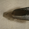
Here is a picture of the transfer case without the shift motor in place and a close-up shot. Notice the marked positions on the transfer case (2H, 4H, 4L) that the selector shaft points towards with the tip. That order is the order of selection as well. In these shots it is pointing towards 2H (2 wheel drive high gear). If worse comes to worse and you are in a tight spot, you can turn this selector with pliers as you can feel the stops (it sets into place with a springy clunk).


It takes a bit of torque to move this selector from one position to the next so Ford had two options: put a huge honking high-torque motor on it or put a smaller low-torque motor on it with geared reduction to get the torque necessary. The second option is best because it weighs less, requires less power to run it, and costs less. This particular geared combination is called a worm-gear drive. There is a large gear that goes on the end of the selector shaft (shown here on the shaft without the gear housing). The teeth are on the edges of the gear and are angled. Notice on the end of the gear there is a pattern. This serves to allow the computer to sense the position of the gear and therefore the selector shaft.

There are six finger-like contacts on the cover that are stationary, and by a series of open/closed circuits, the computer can tell where the selector shaft is pointing. This is pretty important because of the computer has to tell the motor when to start and stop. If the computer doesn‘t know what position it is in, it will default to a fail-safe mode of doing nothing except blinking the lights to let you know it is confused and lost. The six contacts might be a little corroded (mine were), so I took a piece of super-fine sandpaper (600 grit) and cleaned off the corrosion on the ends where they ride against the large gear. I also gave them a slight bend up so that they would have even more spring force pushing them against the gear.

The gear housing serves in a couple of different functions. It is part of the electric motor (contains the brushes and sleeve bearings), it holds the two meshed gears together, and it has a reœstopto keep the large gear from rotating too far in either direction. The next picture shows this housing and the beginning/end stop wedge.

The back of the large gear has a stud with a plastic bushing (cushion) over it that hits the stop. This bushing is what can cause many of the problems with the shift motor losing its place and getting lost. What happens is, over time, this bushing gets deformed and allows the large gear to rotate just enough past the stop to make the computer lose track of the position. To make things worse, the stop wedge in the gear housing is too short to fully engage the plastic bushing, meaning the stop is only pressing against half (front) of the bushing. Here is a picture of this bushing on the back of the large gear. This shift motor hadn't gotten lost (yet) but the crushing is evident. Sometimes you can just flip the bushing over or rotate it so that a different part is getting crushed. Other times the bushing is hardened and broken into several pieces. This is the piece that I suspect is the main culprit behind many shift motor replacements. I think it is a shame that a piece that costs maybe a quarter can end up costing an unknowing consumer hundreds of dollars.

The next picture shows the end bracket, bolts and main case of the motor. The main case has two (very strong) magnets bonded to the inside.
The bolts fit through the end cap shown below. When assembling the end cap, be sure to have it oriented the right way so that the tab from the main case fits into the tab in the end cap (at the 11 position in the photo below). This end cap has a lubricated sleeve bearing as well as a little plate that fits in the end and rides against the motor shaft. This is a grounded connection which is the reason for the tab (the gasket isolates the rest of this end cap from the main case).
Next is the main winding assembly. This has the small screw-gear end that moves the large gear.
The brushes ride against the area shown below. Over time, these contacts can get dirty. I used brake cleaner to easily remove the deposits left by the brushes.
Here is a picture of the gear housing where the motor brushes fit. You can see the two brushes and springs.
The springs press the brushes against the main winding assembly as shown below. This is really the first step in the build-up of the assembly after complete disassembly (and cleaning/re-lubing). I found it easiest to compress the springs with the brushes and hold them back with my fingers while I used my other hand to insert the main winding assembly. After I got it in place it looks like this:
Next you have to put on the main case, which is tricky because the magnets want to pull the assembly out of its place in the gear case. I found that holding the main winding in place with a socket type screwdriver while sliding the case on worked pretty well. This is another place you have to watch out for orientation because of a tab on the front (again for grounding and positioning). After this step the end looks like this:

Then you just put on the end cap and put in the two bolts that hold the motor together. Once you do this, it might be a good idea to try out the motor and run it in both directions (just to be sure the motor is working after reassembly). You can do this by directly applying 12-13V to two pins on the connector that go to the yellow and orange lines. Flip-flop the positive and negative voltage to get it to spin the other way. I used shielded (plastic) female spade connectors on the ends of the jumper lines to be sure that I wasn't applying voltage to any other pins. The motor does start up with a torque-kick (since the rotating mass is pretty heavy), so don't let it get away from you.
The next step is to loosely bolt the motor back onto the case using the four bolts and some sealant (I use Super Black on just about everything). Then you can put the large gear back into place (with the pointer in the right direction). Next is putting on the gear case cover, making sure it is aligned properly. I put a
match mark on the body and cover so I was sure I was getting it aligned back in the stock position. The factory uses the markings cast into the top of the cover and gear case to align it, but since it is on the top and you are underneath, make a mark where you can see it. The case cover is held in place with three T-20 Torx bits. These aren't really expensive (less than $10) and come in handy over and over in a range of DIY projects (any time you want to get into something they don't want you to get into). Here is the cover and Torx bit.
The bottom two bolts that hold on the gear case also holds a bracket in place. To see the bracket and sensor in place, look at the first picture. The sensor looks like this when it is removed:
Once you get the large gear and bracket in place, you can tighten the four bolts the rest of the way. The only thing left is to either zip-tie the wires together or put them back into the corrugated-plastic sheathing that keeps them out of harm's way.
This thread didn't go into checking voltages, the computer control module, checking button function, etc., but there is lots of good info on this site regarding those things. This was just an attempt to show one of the things that keeps happening to people as their Explorers get a few miles and a few years on them. Push the button "click click" nothing!
Edit: I'm adding DeRocha's input on the shift motor because he has been dealing with these things longer than I have and has some good and useful advise and links to more info:
http://www.explorerforum.com/forums/showthread.php?t=97004&page=1&pp=20
He links to a shopping page that has a couple of prices for OEM and aftermarket shift motors for way less than what a dealership would charge (at least around here):
http://shop.store.yahoo.com/dpstore/noname27.html
http://shop.store.yahoo.com/dpstore/affotrca.html
I thought those extra resources might be helpful to somebody.
2nd Edit: I thought that people might want to know that you can get the 11 bit (13 piece) set of 'Tamper Resistant Star Bits' at Checker for $10.49...it has the T-20 that is needed:
http://www.partsamerica.com/PartDet...de=PBI&MfrPartNumber=648666&CategoryCode=3405
 my god i didn't know my clutch had to be depressed in order to get into 4L Thanks a million for the input guys you helped me big time just out of curiousity this is off topic but if i was wanting to climb over obsticles starting at 0 kmh would i use 4l for 4h, see i've never had a truck before and for that matter 4 x4 just wondering when you use 4h and when you use 4L once again i'm sorry that this is off topic.
 You just saved yourself several hundred $$... Most shops would only suggest a new shift motor rather than attempt to fix the old unit...