Oil Coolers | Page 4 | Ford Explorer Forums - Serious Explorations

  • Register Today It's free!

Oil Coolers

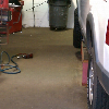
Possible thermostat location

The marked up old photo below indicates a possible location (brown rectangle) for an engine oil cooler thermostat. The full flow remote filter will have to be moved (green arrows) to make room for the thermostat. There will not be much room for the cooler to thermostat connections. A little more room (.5 to .75 inch) can be achieved by moving the cooler toward the A/C condenser support bracket.
OilwTherm.jpg

The black lines around the center filter indicate the larger size of the Amsoil bypass filter.

While waiting to find a suitable oil thermostat I'll reroute the ATF and engine oil hoses to utilize the radiator oil cooler to cool the ATF. That probably can be done without any new parts. I won't move the full flow filter mount or the engine oil cooler until I have a thermostat and determine what fittings/hoses are needed.


Join the Elite Explorers for $20 each year.
Elite Explorer members see no advertisements, no banner ads, no double underlined links,.
Add an avatar, upload photo attachments, and more!
.


That is tidy Dale, I'm still hoping to get mine behind the frame horns(outer side), and install a turbo diesel ATF cooler in place of the condenser.

There is room for a normal FL1A filter ahead of the pockets where the front body mounts are.
 

Attachments

  • Projectthread110.JPG
    Projectthread110.JPG
    108.1 KB · Views: 1,059


Committed to 215 degrees

Well, I'm now committed to a 215 degrees F thermostat to control engine oil flow to the external cooler. I puchased a used Canton P/N 22-480 oil cooler thermostat via eBay for $120 plus $15 shipping.
Canton.jpg

It's the only thermostat I could find with the cooler ports on one side and the line inlet and outlet ports on opposite ends. It was used for 5 hours on a small block ford engine test setup. It comes with -12 O ring to -8 AN male adapters on all ports. Those sell for about $15 each new and the lowest price I could find on the thermostat new was $150 so I think I got a good deal. The body is 3 1/4 inches square and 6 inches tall. It will be a tight fit for the -8 AN hose adapter fittings and hose between the thermostat and the cooler. I may have to have a shop build some very short custom hoses with fittings. There should be no space problems with the vertical connections.


That's a trick thermostat, and I like the 215* rating. That was a good find, Amazon is the cheapest new at $147 shipped, no fittings either.

I wish it was smaller like the block filter adapters, but those are all 160-180* rated.


Would either of you guys happen to know size\thread pitch for the 5r55e test port on the drivers side? Also can I remove the test port without draining the fluid? Ya'll have very clean setups for these remote filters too!


If it's the same as a 4R70W, they are 1/8" NPT threads. I've never worked with those on anything but the AOD, but they are likely still the same.


if u want a nice engine or trans oil cooler look to mazda engine oil cooler,, it is about um 12,, 13 inches high and 24?? wide nice big ports and if u get the whole thing, it is thermo controlled wi/bypass valve built right in, buck


If it's the same as a 4R70W, they are 1/8" NPT threads. I've never worked with those on anything but the AOD, but they are likely still the same.

Thank you!


Optimum ATF filtering & cooling flow

After further research I've decided that the optimum ATF filtering and cooling flow is:

5R55E output > remote filter > radiator cooler > aux coolers > 5R55E input

for the following reasons.

1. The 5R55E external cooling path opens when the temperature in the torque converter exceeds 150 degrees F. If the remote filter is located prior to any coolers there will be less flow restriction. However, locating the filter just prior to the 5R55E input reduces the chance of damaging particles entering the transmission. I may use the latter configuration to simplify installation.

2. While the temperature of the radiator cooler is typically greater than ambient air temperature liquid to liquid heat transfer is many times greater than liquid to air heat transfer for a specific temperature. My remote sensing thermometer typically indicates a radiator temperature of 150 degrees F in the vicinity of the radiator cooler with a 195 degree F thermostat.

3. Auxiliary coolers are mounted in front of the radiator and encounter cooler air than the radiator. If the radiator coolant exceeds 150 degrees F then the auxiliary coolers can lower the ATF temperature. There is no concern during cold weather operation that the ATF temperature will be too low because the transmission internal thermostat will not allow flow thru the external cooling loop if the temperature is less than 150 degrees F. Auxiliary coolers (excluding the radiator cooler) should be in parallel to reduce flow resistance.

Note: The 5R55E has no input suction pump for the external cooling loop.


An added ATF filter should be placed before the coolers if there is no debris spreading through the system(all working well). That protects the coolers if a trans problem occurs.

After a trans failure when there isn't a filter outside, the coolers should be replaced or back flushed very very well. Then it's smart to place a new filter just before the trans.

I'm still planning to install a SD cooler from a big turbo diesel truck. I have the full time flow of a 4R70W, so I'm not sure if I will have to use the radiator or not. I'd prefer to bypass it and try to keep temps as low as possible. I still haven't contacted one of the brands of oil cooler adapters with a thermostat built into them, to see about being able to make one switch at 100-120 degrees. You know they typically switch at 180, which is too high for ATF. I hope that I can find one that is adjustable somehow. Night,


Which port?

I'm searching for documentation that verifies which port (upper or lower) on the 5R55E is the external cooling loop output. BrooklynBay has a thread that shows the coolant return line on the A4LD, 4R44E, 4R55E, 5R55E is the top port: COOLER RETURN LINE CHART My testing by comparing output volumes of each port with a cold transmission indicated that the top port is the output and the lower port is the return. I am disappointed that my ATSG 5R55E manual has no drawing or text that specifies port function. So far I have not been able to find a drawing on the internet but I recall seeing one referenced a couple years ago on the forum. If anyone has one or a link please post it. I want to be sure I'm correct before rerouting ATF coolant lines again.

Edit: I just found a 5R55E external cooling flow test in my 2000 Workshop Manual. It states "Remove the cooler return line (rear fitting) from the fitting on the transmission case." Also "Disconnect the hose from the cooler return line and connect it to the converter outline fitting (front fitting) on the transmission case." I was thinking the two fittings were vertically aligned. Assuming that they are staggered then upon inspection I should be able to answer my question. I found a drawing of the heat shield in the Workshop manual that shows the external cooler ports. The lower one is perpendicular to the case and the upper one is at a 45 degree angle to the case pointing forward. Therefore the lower one (rear fitting) is the return port and the upper one (front fitting) is the supply port. This agrees with my test results.


I would have warmed the fluid and pointed one of the cooler hoses into a pan. Starting it then would quickly point out which is the output line.

I got that from the many people who change their fluid that way. I had to do that to remove a little fluid from my V8 truck a couple years ago. I needed some fluid to refill my V6 truck 5R that was empty, to move it a short ways. I bought new fluid and pulled some from my running 4R and used that old fluid in the 5R. That got me a little new fluid change in my 4R, I had been putting a change off due to plans to swap it out. Things change etc.


thermostat mounting

I removed the under the radiator air deflector and the front bumper to look for a possible mounting location for the engine oil thermostat. The bypass oil filter is not much larger than the standard filter so there is a fair amount of space between them.
FiltersB4.jpg


The inner side of the frame rail behind the bumper mount has potential.
Bumper1.jpg

There's a plastic shield against the frame rail that's in the way.

However, the thermostat body's width (3.25 in) is wider than the distance from the rail to the bumper mounting bolt hole.
Bumper2.jpg

I may be able to raise the thermostat body above the bumper mount bolt/nut but I think there is an outside air temperature sensor in the way. It may be relocatable. I'll have a better view of the area after removing the parking lamps and grille.

The thermostat ports have specific functions because of the way the thermostat is mounted in the body.
OilTstat-1.jpg

I read somewhere that the internal thermostat is used in large diesel trucks and has a greater flow capacity than those typically sold for automotive applications. Some circle track racers with large displacement engines use -10 AN fittings and hoses but for my application I suspect -8 AN will be adequate.


I like that thermostat, I recall when you got it how much they were to buy. I wish those were user adjustable, the internal temperature spring or whatever controls it.

It looks like you need to tighten a fitting at the cooler.


Relocate to the right

I've decided the best way to mount the thermostat is to attach it to the same support that I used for the remote filter mounts. I'll have to relocate all three filter mounts to the right (passenger side) to gain connection clearance between the thermostat and the cooler. The relocation and hose rerouting will give me an opportunity to clean up the entire installation and make it more permanent and reliable (leak free). I want to eliminate hoses between the radiator and the block to make room for a possible electric water pump (associated with an electric cooling fan) and the possible MR2 electric power steering pump.


Reconfigured

I've finally finished relocating the remote filters, the engine oil cooler and installed the engine oil thermostat.
OFLowFull.jpg

The filters and thermostat restrict direct horizontal airflow to the engine oil cooler and the lower part of the A/C condenser and radiator. However, there is ample space between the two to allow upward airflow. Also, the horizontal airflow around the filters provides some cooling.

I had to move the engine oil cooler a little so it's lower AN fitting would line up with the thermostat lower AN fitting.
OFTherm.jpg

The hose loop connects the cooler upper fitting to the thermostat upper fitting. I reinforced the 1/2 inch diameter oil hose with 3/4 inch diameter heater hose to prevent kinking and abrasion.

The block adapter output is connected to the bypass filter and splits to the full flow adapter. I had to use two right angle brass fittings because of the restricted space.
OFATF.jpg


There are no longer any oil lines/hoses between the radiator rear and the engine front.
RadATFFittings.jpg

That frees up some space for the possible electric power steering pump.

Things to do:
Remove AN fittings, apply thread lock, install and tighten them.
Splice engine oil termperature sender wire.
Leak test.
Back Sport out of garage, degrease coolers and then hose off.
Change remote filters and engine oil. Add ATF.
Install front pieces (grille, parking lights, bumper, air deflector, etc.


Busy man there Dale, well done.


temperature data

I collected some interesting temperature data early this afternoon during my leak test. I used my hand held remote reading temperature sensor, my A pillar multi-function temperature gauge and SCT Power Flash data logging to collect the data. Using the hand held the temperature of the radiator, coolers, filters and thermostat before engine start was about 69 degrees. After at least 20 minutes of engine idle the ATF coolers increased to only 94 degrees and the radiator to 82 degrees. The data logged ATF temperature only increased to 111 degrees while the temperature at the inlet to the filter was 104 degrees. The engine oil temperature only increased to 180 degrees and the engine oil cooler increased to 101 degrees. The inlet air temperature averaged 102 degrees even though the ambient temperature was 70 degrees. That's due to pulling air from the engine compartment. (I need to complete the air filter enclosure mod to pull outside air). The engine coolant temperature rapidly increased to 200 degrees (5 degrees more than normal) and stayed there while the radiator temperature only climbed to 82 degrees. I wonder if the 195 thermostat is sticking after being inactive for several weeks.

It is obvious that idling the engine in Park on a cool day does not generate enough heat to achieve the optimum transmission (150) or engine (215) temperature. When hot weather arrives I'll do more data collecting.


That's good data, it tells you that the coolers are doing their job, and the thermostats are working.


Join the Elite Explorers for $20 each year.
Elite Explorer members see no advertisements, no banner ads, no double underlined links,.
Add an avatar, upload photo attachments, and more!
.


start up chain rattle after oil change

Today I idled the engine for 10 minutes to let it achieve operating temperature and then shut it off and removed the oil pan drain plug to let the pan drain. Then I turned the ignition On to purge the Accusump. It took about a minute before the oil pressure "gauge" indicated no pressure. While the 3 quarts of oil from Accusump drained from the pan I removed the old full flow and bypass filters, prefilled the new ones and installed them. Then I inserted the drain plug and added 5 quarts of full synthetic 5W30 oil. I deactivated the Accusump (so it wouldn't fill) to reduce the dry start time. Even though it was only about 40 minutes between shutting off the engine and restarting I still heard timing chain rattle for several seconds while the oil pressure built up. That confirmed my past observation that the springs in the left and right hydraulic tensioners are too weak to prevent chain slap. I say again that Ford should have used ratchet style hydraulic tensioners like the one in the OHV V6
OHVTensioner1.jpg

(photo by Joe Dirt)
and the ones in the 4.6L V8.
97DOHC4_6.jpg


After the oil pressure reached normal I opened the Accusump to fill/pressurize it and then shut the engine off. I still need to add another two quarts or more to raise the oil level to normal. An auxiliary electric oil pump would avoid the annual dry start when I change the oil and filters and allow a constant level of oil in the pan. But the Accusump adds a 3 quart reserve and does not require installing a supply port in the pan. I'm satisfied with it for now.


Back
Top