Brain
Well-Known Member
- Joined
- June 14, 2004
- Messages
- 915
- Reaction score
- 4
- City, State
- Golden, CO
- Year, Model & Trim Level
- '92 4X EB and '91 4X XLT
[ By Glacier991: As a moderator I have taken the liberty to post a prologue here. What this thread represents is the very best in amateur automotive engineering. What Brain (Brian in real life) has done here is to diassemble 10 years of FORD upgrades to the venerable A4LD...and explain them. In the end he shows us that we CAN use a 5R55 gear train in the A4LD, and enjoy the best possible of all worlds.... ALL the A4LD mechanical failings fixed, without the add on troubles the all electronic shift 5R55 suffered at first. To me, this is the very best thread on this entire board. IF you are thinking of rebuilding your A4LD YOU MUST READ this thread. Why? Because when you finish, if you pay attention, you will know more about the evolution of the design that most transmission repairmen. THIS IS AN AWESOME THREAD if you are interested in FORD Explorer transmissions.]
* * * * * * * * * * * * * * * * * * ** * * * * * * * * * * * * * * * * *
This is a current work in progress, so be patient if you think this is incomplete I agree it is at this point.
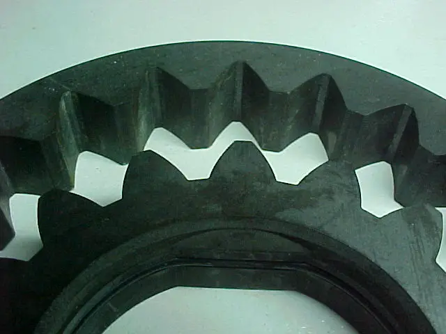
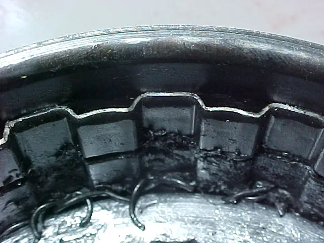
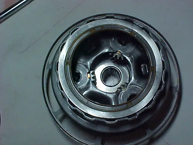
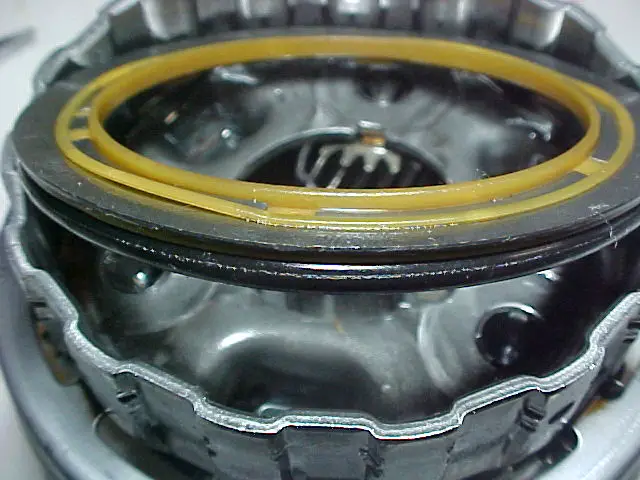
First I'll start off with a little bit of history of why I started this project and why it could be useful and interesting to others. I have a 92 Eddie Bauer that I have used to tow some trailers (kiss my butt U-Haul). The problem is that I didn't follow the owner's manual's directions and I towed in the overdrive shifter position. At 85K miles I had the front seal blow out and it cost a bunch of money to get a cheap seal replaced, but I was on the road so I didn't have the option of doing it myself. That was a failure that set the stage for the second failure. At 125K miles, the overdrive band broke and basically chewed up everything in the front half of the case. That band was worn away faster because of my towing in overdrive, and because I had overheated it at the 85K mark when it ran for a minute or two without fluid. When that band broke, the freed band anchor plate got stuck between the overdrive drum and the case, causing the front half to run off of the centerline (****ed up) and causing parts to collide. This caused enough friction to weld things together that shouldn’t have been.
When a dealership gave me an estimate of $2500 to replace the old A4LD (referred to as the A4 for the rest of this series) with a rebuilt unit, I declined and let the truck sit until I had time and money to fix it myself. When I pulled it apart and saw what kind of damage was done and how many parts I was going to have to replace, I started to research the upgrades that were available to the A4. There are quite a few available out there, but I kept hearing about front seal problems with the A4 that I hadn’t heard of with the 4R55E (the next gen A4 used from ’95-’96, referred to as the 4R for the rest of this series), the 5R55E (the third gen A4 used from ’97-’02, referred to as the 5R for the rest of this series), or the 5R55W (the fourth gen A4 used from ’02 and up, not mentioned again). It seemed to me that hearing this problem over and over again, that somebody would have found a way to fix it. The problem is that there is no “fix†for it if you want to keep all of the A4 as it was produced without using some mix-and-matching of parts from later years. In my opinion, it was a flaw inherent in the design (but it takes some knowledge of fluid dynamics to fully understand the problem). I decided that fixing a bunch of other potential problems wouldn’t be worth it for me if I couldn’t find a way to deal with that front seal and bushing problem.
While I was researching and learning about the A4 and its offspring (which itself originated from the C-3), I found that Ford had redesigned how the lubrication for the front bushing and seal was supplied. I also found out that many of the bushings were eventually replaced with roller bearings and that the numerous thrust washers were replaced by really thin Torrington bearings. If anybody is interested in the A4, they have probably read through Glacier991’s posts about rebuilding the A4 in the most “bulletproof†fashion possible. In those posts he hits the nail on the head at the beginning and end of the series when he said that the best you could do is try to use as many parts and design ideas from the 5R as possible. His efforts inspired me to do this write-up, as well as peaked my curiosity. Hence my journey in hybridization of transmissions, Project Fankentranny, began.
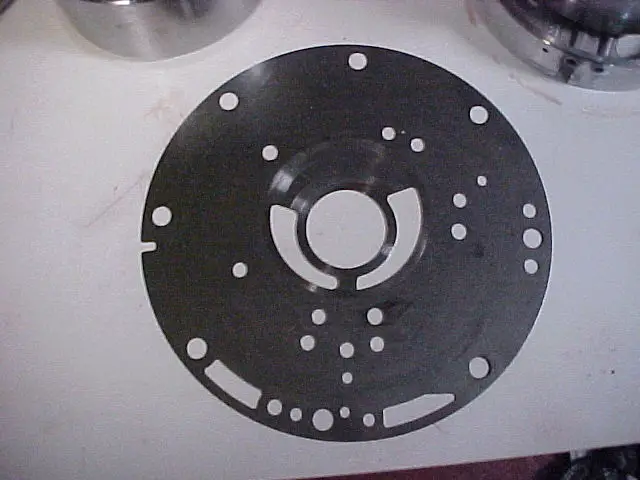
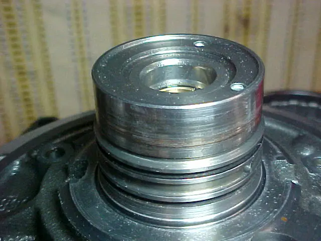
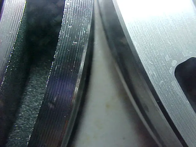
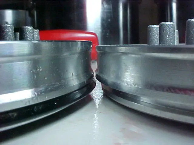
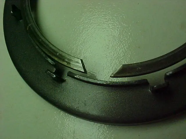
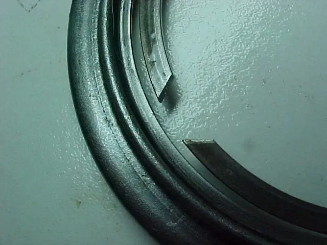
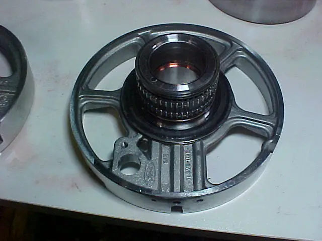
First I wanted to find a solution to the front seal lubrication issue. I found that the A4 and the 4R bellhousings were the same except for a different design for the lubrication of the front bushing, an extra pump bolthole, and one elongated hole feeding the case. The 5R bellhousing was the same as the 4R, except the pocket for the starter was shaped differently (which makes sense because it was behind a different motor). So, if I wanted to have the updated way of lubricating the front bushing and seal, and keep the standard starter setup and bolt pattern, a 4R bellhousing was a must. It serves as my “adaptor plateâ€.
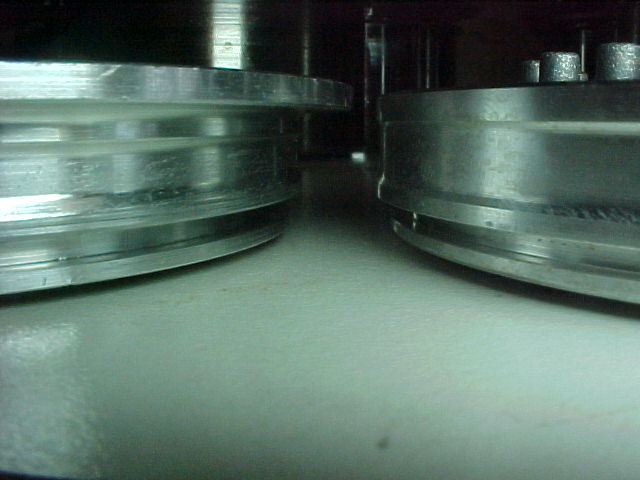
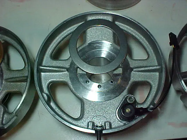
A4/4R bellhousing front
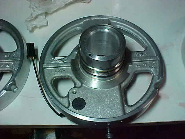
5R bellhousing front (notice the different starter pocket shape)
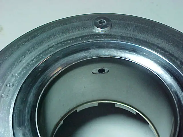
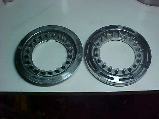
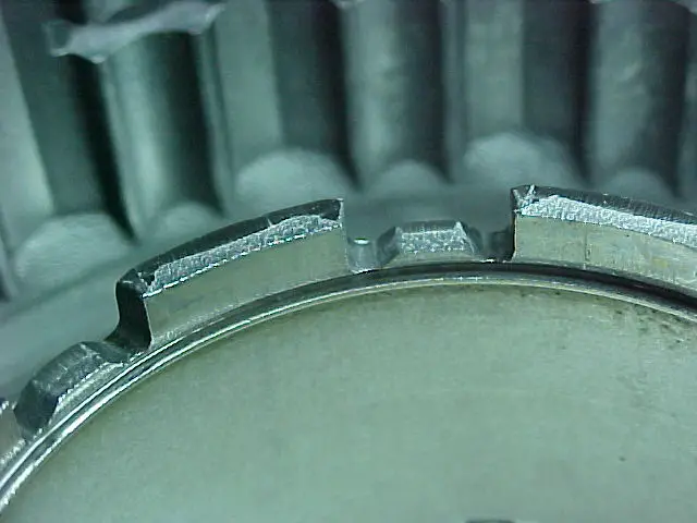
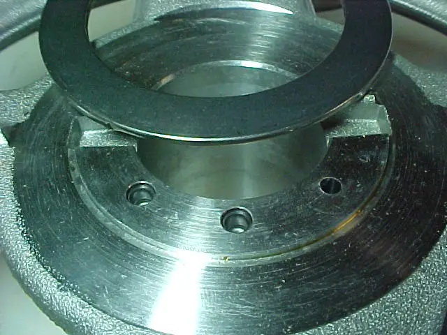
A4 bellhousing back

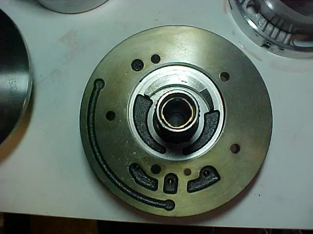
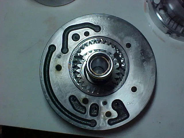
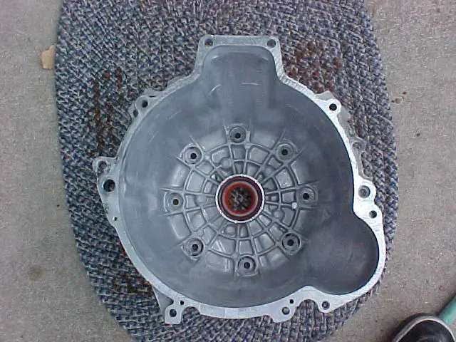
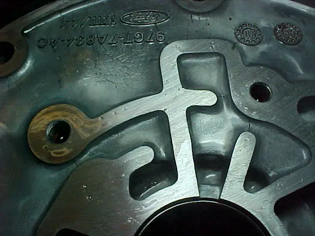
4R/5R bellhousing back - stock
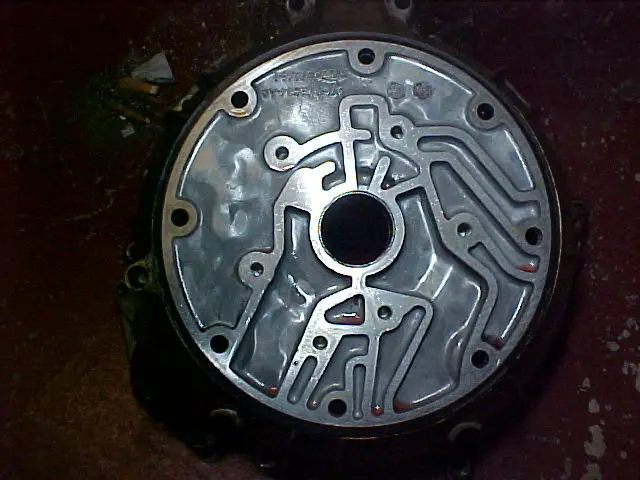
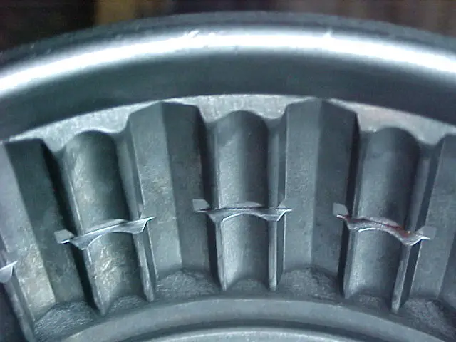
4R/5R bellhousing back - stock lube pathways
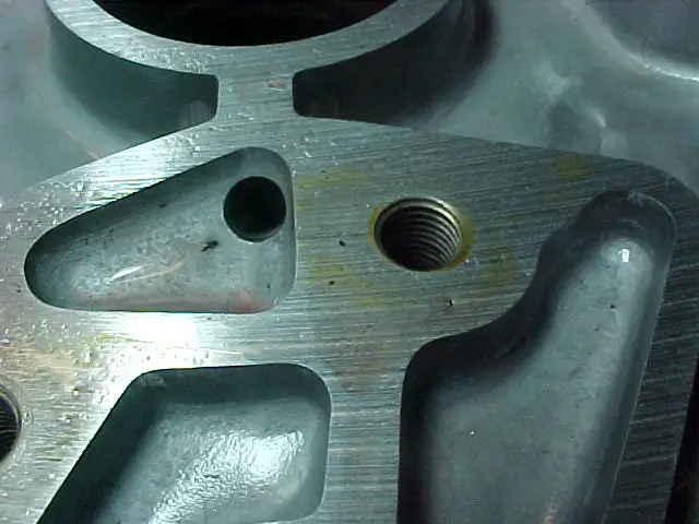
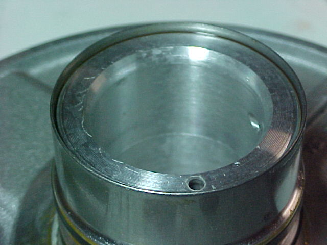
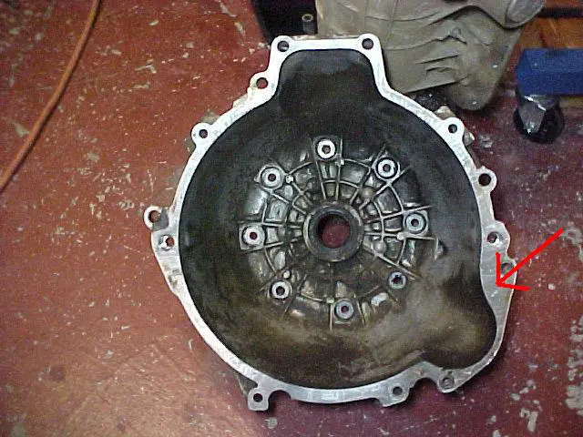
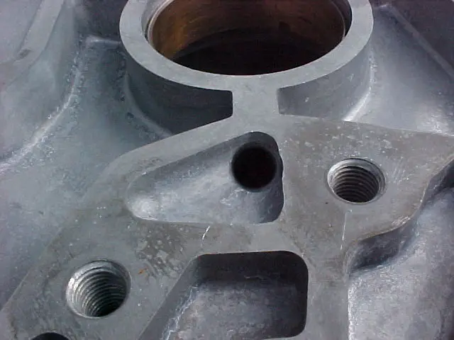
4R bellhousing back - modified lube pathways (bigger drainback hole and cut back supply restrictions)

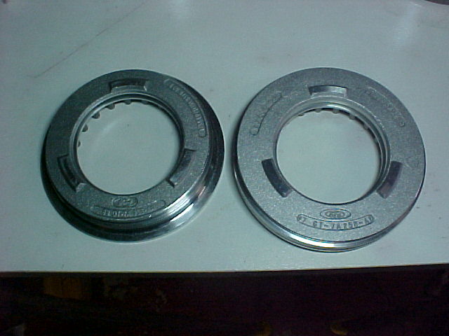
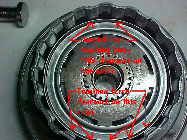
Notice that the part numbers (year reference) are stamped in the back of the bellhousings with the A4 having the number starting 90GT (starting in '90), the 4R has a number starting 95GT ('95), and the 5R starting 97GT ('97). The right one to wark as an adaptor between the 4.0L and using the new way of lubricating the front seal and bushing is the 95GT.
* * * * * * * * * * * * * * * * * * ** * * * * * * * * * * * * * * * * *
This is a current work in progress, so be patient if you think this is incomplete I agree it is at this point.
First I'll start off with a little bit of history of why I started this project and why it could be useful and interesting to others. I have a 92 Eddie Bauer that I have used to tow some trailers (kiss my butt U-Haul). The problem is that I didn't follow the owner's manual's directions and I towed in the overdrive shifter position. At 85K miles I had the front seal blow out and it cost a bunch of money to get a cheap seal replaced, but I was on the road so I didn't have the option of doing it myself. That was a failure that set the stage for the second failure. At 125K miles, the overdrive band broke and basically chewed up everything in the front half of the case. That band was worn away faster because of my towing in overdrive, and because I had overheated it at the 85K mark when it ran for a minute or two without fluid. When that band broke, the freed band anchor plate got stuck between the overdrive drum and the case, causing the front half to run off of the centerline (****ed up) and causing parts to collide. This caused enough friction to weld things together that shouldn’t have been.
When a dealership gave me an estimate of $2500 to replace the old A4LD (referred to as the A4 for the rest of this series) with a rebuilt unit, I declined and let the truck sit until I had time and money to fix it myself. When I pulled it apart and saw what kind of damage was done and how many parts I was going to have to replace, I started to research the upgrades that were available to the A4. There are quite a few available out there, but I kept hearing about front seal problems with the A4 that I hadn’t heard of with the 4R55E (the next gen A4 used from ’95-’96, referred to as the 4R for the rest of this series), the 5R55E (the third gen A4 used from ’97-’02, referred to as the 5R for the rest of this series), or the 5R55W (the fourth gen A4 used from ’02 and up, not mentioned again). It seemed to me that hearing this problem over and over again, that somebody would have found a way to fix it. The problem is that there is no “fix†for it if you want to keep all of the A4 as it was produced without using some mix-and-matching of parts from later years. In my opinion, it was a flaw inherent in the design (but it takes some knowledge of fluid dynamics to fully understand the problem). I decided that fixing a bunch of other potential problems wouldn’t be worth it for me if I couldn’t find a way to deal with that front seal and bushing problem.
While I was researching and learning about the A4 and its offspring (which itself originated from the C-3), I found that Ford had redesigned how the lubrication for the front bushing and seal was supplied. I also found out that many of the bushings were eventually replaced with roller bearings and that the numerous thrust washers were replaced by really thin Torrington bearings. If anybody is interested in the A4, they have probably read through Glacier991’s posts about rebuilding the A4 in the most “bulletproof†fashion possible. In those posts he hits the nail on the head at the beginning and end of the series when he said that the best you could do is try to use as many parts and design ideas from the 5R as possible. His efforts inspired me to do this write-up, as well as peaked my curiosity. Hence my journey in hybridization of transmissions, Project Fankentranny, began.
First I wanted to find a solution to the front seal lubrication issue. I found that the A4 and the 4R bellhousings were the same except for a different design for the lubrication of the front bushing, an extra pump bolthole, and one elongated hole feeding the case. The 5R bellhousing was the same as the 4R, except the pocket for the starter was shaped differently (which makes sense because it was behind a different motor). So, if I wanted to have the updated way of lubricating the front bushing and seal, and keep the standard starter setup and bolt pattern, a 4R bellhousing was a must. It serves as my “adaptor plateâ€.
A4/4R bellhousing front
5R bellhousing front (notice the different starter pocket shape)
A4 bellhousing back
4R/5R bellhousing back - stock
4R/5R bellhousing back - stock lube pathways
4R bellhousing back - modified lube pathways (bigger drainback hole and cut back supply restrictions)
Notice that the part numbers (year reference) are stamped in the back of the bellhousings with the A4 having the number starting 90GT (starting in '90), the 4R has a number starting 95GT ('95), and the 5R starting 97GT ('97). The right one to wark as an adaptor between the 4.0L and using the new way of lubricating the front seal and bushing is the 95GT.