SOHC V6 Timing Chain Saga | Page 19 | Ford Explorer Forums - Serious Explorations

  • Register Today It's free!

SOHC V6 Timing Chain Saga

That looks great. When you get more time and rebuilding it, send some visible things to Jon to powder coat. That will stand out, and survive in the engine bay.


Join the Elite Explorers for $20 each year.
Elite Explorer members see no advertisements, no banner ads, no double underlined links,.
Add an avatar, upload photo attachments, and more!
.


I can second that...

Finishing up installing the new shortblock and the rest of the top end in my Explorer.. I had Turdle powdercoat the valve covers and the water neck in bright red and they really do stand out in the engine bay...I wish the rest of the components didn't hide the valve covers though...I may get a set of brackets and have them and maybe the exhaust manifolds powder coated as well.. Especially if the powdercoat would hold up the heat...
 

Attachments

  • P5040151.JPG
    P5040151.JPG
    67.7 KB · Views: 2,129
  • P5040153.JPG
    P5040153.JPG
    70.5 KB · Views: 2,059


Finishing up installing the new shortblock and the rest of the top end in my Explorer.. I had Turdle powdercoat the valve covers and the water neck in bright red and they really do stand out in the engine bay...I wish the rest of the components didn't hide the valve covers though...I may get a set of brackets and have them and maybe the exhaust manifolds powder coated as well.. Especially if the powdercoat would hold up the heat...

As an ex powder coater (mind you that was over 15yrs ago and now a chef) I am quite sure it wont hold up. Powder coat is baked @ between 180c and 200c,
depending on colour, for 10 mins. Any longer or hotter and it will start to burn and discolour. Any other engine component can be done. Epoxy powder coat is the best as it is more resistant to corrosion.
Ceramic coating is resistant to very high temps but may not be worth the cost.
I think hi temp paint is the way to go. Its cheap and any painted exhaust manifold looks good.

What made me want to be a chef? Being a powder coater!


Ask Jon about a pair or two of exhaust manifolds that he has coated. It's been a long long time, but it was a special material that he used. I haven't read of how those are doing since that though.


Seperation wasn't the issue...

Your engine is really looking good! Obviously you solved your problem in separating the old engine from the transmission.

It was pushing the convertor backwards away from the flexplate...I marked the plate and the stud that was sticking through the plate and reinstalled the engine indexed with the flexplate to that same stud...Pulling the old one took maybe 30 mins... Installing the new shortblock and indexing to the convertor stud took a couple of hours to master...

Even with the engine out I could not get that convertor to slide back...And it is completely inside the front pump...Today, at 223 pm CDT, I fired the new engine up and put the first 20-30 mins of run time on it...Then I drove it for about 5 miles...Tranny is working fine, engine is working fine, I didn't start out to replace the shortblock but it is a done deal now!!!


Congratulations!

. . . Today, at 223 pm CDT, I fired the new engine up and put the first 20-30 mins of run time on it...Then I drove it for about 5 miles...Tranny is working fine, engine is working fine, I didn't start out to replace the shortblock but it is a done deal now!!!

Way to go on your new short block running good! If you used a lot of prelube I suggest that you immediately change the oil filter.


so how do u change just the rear cassette? is there any way to get it done without fully disassembling the chain and gear?


Pull the engine

To replace the rear cassette (chain, guide assembly, sprockets) you must either pull the engine or pull the transmission. I believe only one member has done it by pulling the transmission. The flexplate/flywheel has to come off. It is extremely awkward to work under the vehicle, especially if you don't have a lift.


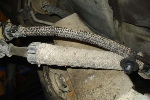
Today I tackled the power steering pump. My goal was to completely disconnect it from the engine without disconnecting any of the fluid lines. I did not remove the water pump pulley or the power steering pump pulley. There are holes in the power steering pump pulley that allow removal of the pump mounting bolts without removing the pulley. I left one of the three bolts in place until after disconnecting the reservoir mounting bolts. I disconnected the hose positioning bracket below the pump but overlooked the one under the A/C compressor that is visible from the left fender well. The photo below shows the steering pump after I was able to work it past the water pump pulley.
View attachment 58170
There's a plastic pin on the bottom of the reservoir that fits in the mounting bracket. The reservoir must be raised the length of the pin before the entire assembly can be moved forward and down out of the way. I realized there was still a hose positioning attachment in place when I tried to raise the reservoir. The hose has to slide past the A/C compressor before the steering assembly can be lowered out of the way. 
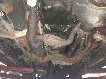
It is necessary to disconnect the A/C compressor clutch electrical connector to get the hose past. It took me about 20 minutes to get the connector to release because it's not the squeeze type like I assumed. The photo below shows how neatly the power steering assembly can be tucked out of the way.
View attachment 58178

I'm having the same problem. I could not get the connector off so it's still attached. Do you remember how you got it off?

Also I had a problem getting the compressor moved because of the studs. I had to use pliers to remove the studs. Then I was able to move it to the side.

Cliff


A/C compressor connector

The photos of the A/C compressor connector shown below are poor quality (My camera was too close) but good enough for you to see the mechanical configuration.
ACCnx1.jpg

The squeeze release lever is on the slender side of the connector. It is easy to release but getting your hand in the correct position is tough.
ACCnx2.jpg


Thanks Dale....I got it off with your help.

I have almost every thing disconnected. I was looking for a plate to remove to get at the flex plate bolts but I see now that they are removed in the exposed area where the starter was.

Soon I will find out what happened to this motor.


CJ


Odds & Ends

Today I took care of some odds and ends that are easy to do when the engine is on a stand. First I replaced the dried out and no longer sticking tape on the electrical and vacuum looms with black electrical tape.

When I removed the dipstick holder from the block the large, thick O ring that fits between the holder flange and the block fell apart. I replaced it with a new one as identified by the green arrow in the photo below.
DipStick.jpg

I also checked the condition of the smaller O ring that fits inside the block as identified by the red arrow. I bent the dipstick holder support bracket so when bolted in place the flange would exert pressure on the large O ring.

My EGR tube heat sleeving has unraveled a little at each end so I installed hose clamps as indicated by the red arrows in the photo below. The heat sleeving helps the EGR tube retain heat which reduces condensation in the DPFE sensor tubes/hoses.
 

Attachments

  • EGRTube.jpg
    EGRTube.jpg
    76.7 KB · Views: 2,264


My EGR tube heat sleeving has unraveled a little at each end so I installed hose clamps as indicated by the red arrows in the photo below. The heat sleeving helps the EGR tube retain heat which reduces condensation in the DPFE sensor tubes/hoses.

Too funny! This sleeve is drawn in as frayed and unraveled in the diagram of the EGR tube in my manual.

I hate working near that stuff. I just have to look at it and I get splinters.


Thermostat housing reinforcement

When I installed my 00M12 kit I removed the engine coolant temperature sensor and the engine temperature sender from the thermostat housing to gain more room to remove and install the hydraulic tensioner. I was luckier than some other members who had the brass fitting spin in the plastic housing. When I installed the sensors I used thread sealant to prevent leakage. I anticipate that the thread sealant will require additional force to remove the sensors in the future.

Since I had the thermostat housing out while replacing the timing chain components I decided to try reinforcing the housing. First I cleaned the exposed portion of the brass fitting and the plastic surrounding it as shown in the two photos below with a small wire brush and then cloth.
ThrmHsg1.jpg

ThrmHsg2.jpg


Next I mixed some two part epoxy and very carefully applied it to the intersection of the brass fitting and the plastic housing as identifed with the arrows in the photo below.
ThrmHsg3.jpg

I made sure not to get any epoxy on the sensor threads. Hopefully, I won't know if the reinforcement worked until my odometer has accumulated another 75,000 miles and I replace the front hydraulic tensioner again.


It's amazing how expensive those housings are. You may of saved yourself by doing this.


Dale, you might want to upgrade that when you rebuild. The later model SOHC got a revised upper and lower housing, which is much cheaper and different sensors which mount differently.

Search for the threads here where others came up with a great solution for the older SOHC. You can buy the cheaper upper housing from aftermarket sources, and make it work with the older lower housing. What I remember is that they bought the newer sensors and the clips to install them, and removed the bolt hole sleeves which are for the newer lower housing. So you end up with all the upper parts new and mount them on the old lower. I think the parts total was under $100, say $60 for the lower housing plus the sensors and clips.

My SOHC had no leaking there and I never loosened those sensors to work on mine. If they are never touched, they may last a long time.


As you know that happened to me. I upgraded to the new housing and sensors for around $100 since the stealer wanted $320 for the older version housing.

Mine broke on the sensor closes to the inlet. It installs to a brass fitting which is encased in plastic molded around it. Mine did not crack at the top but on the encased nut side in the housing. When that happened the fitting just spun as I tried to tighten. I'm sure it broke when I uninstalled the sensor to make room to loosen the tensioner. I wasn't even to the point of tightening when I went to reinstall it. I was going to try and epoxy the encased nut inside the housing but opted for the newer cheaper housing.


CJ


It seems like that first design is a one use only. Left alone they may never leak, but most happen when the sensors are removed. I was fortunate that my wrench and socket went on the tensioner without moving the sensor. It was very very tight, a rub, but it worked.


Join the Elite Explorers for $20 each year.
Elite Explorer members see no advertisements, no banner ads, no double underlined links,.
Add an avatar, upload photo attachments, and more!
.


I've removed these sensors a couple of time. I guess I'm the lucky one because there still okay - *knock on wood*

2000StreetRod - Forgive me..You may of already went over this. When you timed your cams, did you use a degree wheel and advance the timing 2 degree's?


Back
Top