Modifications Performed
Removed side step bars (post #3)
Replaced single row (1 inch thick) radiator with double row (2 inch thick) radiator (post #3)
Installed towing wiring and bumper mounted ball (post #8)
Replaced stock right caster/camber bolts with large range adjustable bolts (post #9)
Replaced 2 piece right upper control arm with 1 piece arm (post #9)
Installed throttle cable tensioner to reduce slack (post #10)
Lowered rear 0.75 inches by replacing monoleaf rear springs with 3 leaves plus overload leaf springs (post #14)
Installed Edelbrock IAS lowering rear shocks (post #15)
Installed Akimoto racing air filter (post #16)
Replaced stock left caster/camber bolts with large range adjustable bolts (post #18)
Installed Edelbrock IAS lowering front shocks (post #19)
Lowered front 0.75 inches (post #20)
Modified front bump stops (post #20)
Relocated stock external ATF cooler (post #24)
Added second external ATF cooler (post #24)
Installed remote full flow ATF filter & temperature sender (post #24)
Installed remote full flow & bypass engine oil filters & temperature sender (post #25)
Installed external engine oil cooler (post #25)
Installed A pillar pod mounted multi-function temperature gauge (post #27)
Installed two 1.75 inch internal diameter cold air ducts to air filter enclosure (post #28)
Removed 1 3/4 inch diameter inlet cone from air filter enclosure (post #28)
Installed wideband O2 sensor in left downpipe & pod pillar mounted wideband air/fuel ratio meter (post #29)
Replaced stock 65mm throttle body with a Ford prototype 75mm racing ported and polished throttle body (post #31)
Removed throttle cable tensioner & installed 75mm to 65mm throttle body spacer (post #31)
Replaced stock 55mm MAF sensor with 90mm Lightning MAF sensor (post #32)
Designed & built MAF sensor amplifier to compensate for MAF sensor upgrade (post #35)
Replaced Akimoto cone air filter with Spectre 4 inch diameter outlet cone filter (post #35)
Replaced petroleum based rear axle lubricant with synthetic lubricant (post #37)
Installed oil pressure sending unit at oil pressure switch port (post #41)
Modified A pillar pod muti-function temperature gauge to display relative oil pressure (post #43)
Modified PCV valve associated hose configuration (post #46)
Replaced & adjusted mechanical idle speed adjustment screw (post #50)
Replaced petroleum based engine oil with synthetic oil (post #51)
Removed MAF sensor amplifier and loaded custom tune from Henson Performance (post #55)
Painted engine block Ford blue (post #58)
Painted exhaust manifolds silver (post #58)
Reinforced thermostat housing (post #60)
Installed under hood remote starter control (post #63)
Replaced main intake tube C clamps with T-bolt clamps (post #64)
Installed Accusump 3 quart engine pre-oiler (post #66)
Replaced 5R55E reverse servo gaskets with D ring gaskets (post #70)
Installed Canton Racing 215 deg F thermostat for engine oil cooler (post #80)
Replaced stock front sway bar bushings & end links with polyurethane bushings & links from Energy Suspension (post #81)
Replaced stock exhaust system from manifold outlets back with high flow cats, Y pipe, muffler, tailpipe and turndown (post #82)
Replaced stock fuel pump with Aeromotive Stealth 340 lph high flow pump (post #85)
Replaced stock 130 amp 4G alternator with custom built 240 amp 4G alternator (post #87)
Installed Banshee/M90 supercharger (post #88)
Installed electronic fuel pressure controller (post #90)
Upgraded electronic fuel pressure controller (post #93)
Upgraded engine gauges (post #94)
Modified hood for M90 pulley clearance (post #95)
Purchased SCT's Advantage III Racer Pro software tuning package to generate my own tunes (post #97)
Upgraded intercooler heat exchanger (post #98)
Installed thermostat metal lower housing (post #99)
Maintenance Performed
Replaced windshield (post #2)
Replaced tires with BF Goodrich Long Trail T/A Tour P235/75XL108T 15 inch tires (post #2)
Replaced hood lift cartridges (post #3)
Replaced left lower control arm (post #17)
Installed 00m12 kit intake manifold gaskets, left chain tensioner & oil galley reducer (post #45)
Replaced PCV valve (post #46)
Replaced fuel filter (post #48)
Replaced camshaft timing cassettes, tensioner & guide, primary chain & sprockets (post #56)
Degunked engine internals (post #58)
Replaced radiator cooling fan blade (post #59)
Replaced rear main seal (post #61)
Replaced water pump (post #68)
Replaced 5R55E transmission filter, blown valve body separator plate gasket, broken solenoid mounting bracket (post #70)
Replaced split flexible fuel hose from tank to rigid fuel line (post #74)
Replaced serpentine belt & tensioner pulley (post #78)
Repaired rear hatch strikers (post #79)
Replaced rear axle vent hose (post #86)
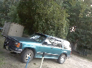
The photos below show my 2000 Explorer Sport that I purchased from a tow truck driver in May, 2009. It had been abandoned on the freeway and the tow truck driver obtained ownership as payment for the towing fee. The only thing that prevented the vehicle from running was a bad camshaft sensor. The tow truck driver replaced it, the spark plugs, and engine oil and filter.

These photos were taken after considerable cleaning and polishing. The external paint is Toreador Red and the interior is gray. The body is in fairly good condition with a few minor dings and no visible rust.
I purchased my Sport for $3,000 in Concord, North Carolina. It had 150,000 miles on the odometer and was dirty inside and out. Although it doesn't show in the photo below there are multiple cracks in the windshield.

I retired on July 4 and decided to search for a smaller SUV to replace my 1997 Tahoe shown in the background. I did considerable research and narrowed my search to a two door. While I have owned Jeeps for most of my driving life, I knew from past experience that the Cherokee Sport made me feel cramped when driving. I also eliminated the Blazer for the same reason. I eventually settled on the Explorer liking the simplicity and handling of front engine rear wheel drive. 2000 was the last year that Ford made the body style I preferred so that's what I looked for. Toreador Red was my first color choice so I was thrilled when an advertisement for one showed up on Craigslist.
It rained about one third of the way home to Greenville, South Carolina. The cracked windshield caused the windshield wipers to smear which made the drive home somewhat stressful. Adding to the stress was an alarm that sounded about every fifteen minutes because one of the sensors on the rear hatch was misaligned. Another aggravation was failure of the power side mirrors to adjust. I was also concerned about the tires. The original spare was on the right front since one of the tires was flat.

The other three tires had virtually no tread remaining. I drove a maximum of 55 miles per hour when there was no rain and 50 miles per hour in the rain.
The vehicle was originally purchased in Texas as indicated by the license plate.

You can see that the left rear is considerably lower than the right. I bought my Sport as a utility vehicle but also as a long term test bed for experimentation. I am an electrical engineer by degree and a former senior systems engineer. I will be trying various performance and fuel economy modifications on my Sport for many years. I intend to keep it for the remainder of my driving years.
Removed side step bars (post #3)
Replaced single row (1 inch thick) radiator with double row (2 inch thick) radiator (post #3)
Installed towing wiring and bumper mounted ball (post #8)
Replaced stock right caster/camber bolts with large range adjustable bolts (post #9)
Replaced 2 piece right upper control arm with 1 piece arm (post #9)
Installed throttle cable tensioner to reduce slack (post #10)
Lowered rear 0.75 inches by replacing monoleaf rear springs with 3 leaves plus overload leaf springs (post #14)
Installed Edelbrock IAS lowering rear shocks (post #15)
Installed Akimoto racing air filter (post #16)
Replaced stock left caster/camber bolts with large range adjustable bolts (post #18)
Installed Edelbrock IAS lowering front shocks (post #19)
Lowered front 0.75 inches (post #20)
Modified front bump stops (post #20)
Relocated stock external ATF cooler (post #24)
Added second external ATF cooler (post #24)
Installed remote full flow ATF filter & temperature sender (post #24)
Installed remote full flow & bypass engine oil filters & temperature sender (post #25)
Installed external engine oil cooler (post #25)
Installed A pillar pod mounted multi-function temperature gauge (post #27)
Installed two 1.75 inch internal diameter cold air ducts to air filter enclosure (post #28)
Removed 1 3/4 inch diameter inlet cone from air filter enclosure (post #28)
Installed wideband O2 sensor in left downpipe & pod pillar mounted wideband air/fuel ratio meter (post #29)
Replaced stock 65mm throttle body with a Ford prototype 75mm racing ported and polished throttle body (post #31)
Removed throttle cable tensioner & installed 75mm to 65mm throttle body spacer (post #31)
Replaced stock 55mm MAF sensor with 90mm Lightning MAF sensor (post #32)
Designed & built MAF sensor amplifier to compensate for MAF sensor upgrade (post #35)
Replaced Akimoto cone air filter with Spectre 4 inch diameter outlet cone filter (post #35)
Replaced petroleum based rear axle lubricant with synthetic lubricant (post #37)
Installed oil pressure sending unit at oil pressure switch port (post #41)
Modified A pillar pod muti-function temperature gauge to display relative oil pressure (post #43)
Modified PCV valve associated hose configuration (post #46)
Replaced & adjusted mechanical idle speed adjustment screw (post #50)
Replaced petroleum based engine oil with synthetic oil (post #51)
Removed MAF sensor amplifier and loaded custom tune from Henson Performance (post #55)
Painted engine block Ford blue (post #58)
Painted exhaust manifolds silver (post #58)
Reinforced thermostat housing (post #60)
Installed under hood remote starter control (post #63)
Replaced main intake tube C clamps with T-bolt clamps (post #64)
Installed Accusump 3 quart engine pre-oiler (post #66)
Replaced 5R55E reverse servo gaskets with D ring gaskets (post #70)
Installed Canton Racing 215 deg F thermostat for engine oil cooler (post #80)
Replaced stock front sway bar bushings & end links with polyurethane bushings & links from Energy Suspension (post #81)
Replaced stock exhaust system from manifold outlets back with high flow cats, Y pipe, muffler, tailpipe and turndown (post #82)
Replaced stock fuel pump with Aeromotive Stealth 340 lph high flow pump (post #85)
Replaced stock 130 amp 4G alternator with custom built 240 amp 4G alternator (post #87)
Installed Banshee/M90 supercharger (post #88)
Installed electronic fuel pressure controller (post #90)
Upgraded electronic fuel pressure controller (post #93)
Upgraded engine gauges (post #94)
Modified hood for M90 pulley clearance (post #95)
Purchased SCT's Advantage III Racer Pro software tuning package to generate my own tunes (post #97)
Upgraded intercooler heat exchanger (post #98)
Installed thermostat metal lower housing (post #99)
Maintenance Performed
Replaced windshield (post #2)
Replaced tires with BF Goodrich Long Trail T/A Tour P235/75XL108T 15 inch tires (post #2)
Replaced hood lift cartridges (post #3)
Replaced left lower control arm (post #17)
Installed 00m12 kit intake manifold gaskets, left chain tensioner & oil galley reducer (post #45)
Replaced PCV valve (post #46)
Replaced fuel filter (post #48)
Replaced camshaft timing cassettes, tensioner & guide, primary chain & sprockets (post #56)
Degunked engine internals (post #58)
Replaced radiator cooling fan blade (post #59)
Replaced rear main seal (post #61)
Replaced water pump (post #68)
Replaced 5R55E transmission filter, blown valve body separator plate gasket, broken solenoid mounting bracket (post #70)
Replaced split flexible fuel hose from tank to rigid fuel line (post #74)
Replaced serpentine belt & tensioner pulley (post #78)
Repaired rear hatch strikers (post #79)
Replaced rear axle vent hose (post #86)
The photos below show my 2000 Explorer Sport that I purchased from a tow truck driver in May, 2009. It had been abandoned on the freeway and the tow truck driver obtained ownership as payment for the towing fee. The only thing that prevented the vehicle from running was a bad camshaft sensor. The tow truck driver replaced it, the spark plugs, and engine oil and filter.
These photos were taken after considerable cleaning and polishing. The external paint is Toreador Red and the interior is gray. The body is in fairly good condition with a few minor dings and no visible rust.
I purchased my Sport for $3,000 in Concord, North Carolina. It had 150,000 miles on the odometer and was dirty inside and out. Although it doesn't show in the photo below there are multiple cracks in the windshield.
I retired on July 4 and decided to search for a smaller SUV to replace my 1997 Tahoe shown in the background. I did considerable research and narrowed my search to a two door. While I have owned Jeeps for most of my driving life, I knew from past experience that the Cherokee Sport made me feel cramped when driving. I also eliminated the Blazer for the same reason. I eventually settled on the Explorer liking the simplicity and handling of front engine rear wheel drive. 2000 was the last year that Ford made the body style I preferred so that's what I looked for. Toreador Red was my first color choice so I was thrilled when an advertisement for one showed up on Craigslist.
It rained about one third of the way home to Greenville, South Carolina. The cracked windshield caused the windshield wipers to smear which made the drive home somewhat stressful. Adding to the stress was an alarm that sounded about every fifteen minutes because one of the sensors on the rear hatch was misaligned. Another aggravation was failure of the power side mirrors to adjust. I was also concerned about the tires. The original spare was on the right front since one of the tires was flat.
The other three tires had virtually no tread remaining. I drove a maximum of 55 miles per hour when there was no rain and 50 miles per hour in the rain.
The vehicle was originally purchased in Texas as indicated by the license plate.
You can see that the left rear is considerably lower than the right. I bought my Sport as a utility vehicle but also as a long term test bed for experimentation. I am an electrical engineer by degree and a former senior systems engineer. I will be trying various performance and fuel economy modifications on my Sport for many years. I intend to keep it for the remainder of my driving years.