Ford TCC ground problem outlined in the April 2006 Gears magazine. | Ford Explorer Forums - Serious Explorations

  • Register Today It's free!

Ford TCC ground problem outlined in the April 2006 Gears magazine.

BrooklynBay

Moderator & long time member.
Staff member
Moderator
Elite Explorer
Joined
November 11, 2005
Messages
56,687
Reaction score
1,186
City, State
Brooklyn, NY
Year, Model & Trim Level
88 89 93 95 96 Aerostars
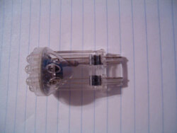
There was an interesting article just published in the April 2006 issue of Gears Magazine which addressed an issue about LED rear taillight bulbs preventing TCC solenoid engagement. The computer assumes that the brakes are applied since it only sees a positive (+) voltage from its built in bias resistor, and the brake pedal switch. The rear bulbs are suppose to pull down this voltage to ground (-). Here is the link to this article: http://www.gearsmagazine.com/images/issues/4_2006/2006_04_38.pdf. I've heard about LED bulbs preventing mechanical flashers from working properly, but not anything related to the transmission's operation. There are bias resistors which could be used in that application to help prevent that problem, but this article just recommends not using them at all in this particular case.


Join the Elite Explorers for $20 each year.
Elite Explorer members see no advertisements, no banner ads, no double underlined links,.
Add an avatar, upload photo attachments, and more!
.


Good to know!


I'm sure that this information is not well known. Somebody should contact one of these LED manufacturers, and ask them to make a low impedance version for Ford vehicles. They have low impedance shunts (resistors) which could be used, but they have to be high wattage, and will throw off a lot of heat. There could be some sort of external resistor that is in a ceramic case, but would require splicing. It would discourage the average person from putting them on their vehicle. Maybe there is a way to just add a shunt directly onto the brake wiring near the brake pedal switch. It should be researched since a lot of people are switching to LED bulbs.


The LED bulbs have a much lower resistance. The issue is that it is so much lower that the PCM detects the lack of needed resistance all of the time(brakes applied). Would not a resistor in line with the LED bulbs provide the needed impedance? The LED makers could help by providing their bulbs specs, and have resistors available that are properly enclosed. Regards,


I have been having an intermittent "no lock up" for a while now-

it hasn't happened for quite a while, but when it does, I get no indication whatsoever there is any malfunction-no codes-no stored codes.
disconnecting the battery always fixes it though--

I am attributing it to my lousy pro m maf-but you know-I do have those rear led's--and they are in the tail-brake lights--hmmmm interesting--

You know what else I noticed about them? They make my third brake light slightly flicker at night with PATS armed--

weird huh?


LEDs require low voltage, and current. In order to use them on a 12 volt system, they must use a built in bias resistor to prevent them from burning out. This set up will increase their series resistance. The bulbs have a high resistance without an external parallel shunt. The shunt simulates the resistance of a regular light bulb with a filament. The problem is that it doesn't pull the voltage down to ground from a positive level. Jon, could you take a resistance measurement of your LED bulb, and compare it to a regular bulb?


Oops, so the LED's produce more resistance than a normal filament bulb? I had that wrong then, using LED's would take more thought.

What is the resistance of the OEM tail lights, brake lights, and then how much for an OEM relay? If the relay resistance is the same, or less and with a resistor can equal the OEM bulb, there's an answer.

Jon I didn't know that you had LED's, that can definitely affect the PCM brake sensing circuit. Let me know what turns up, I may do that someday also.


LEDs require low voltage, and current. In order to use them on a 12 volt system, they must use a built in bias resistor to prevent them from burning out. This set up will increase their series resistance. The bulbs have a high resistance without an external parallel shunt. The shunt simulates the resistance of a regular light bulb with a filament. The problem is that it doesn't pull the voltage down to ground from a positive level. Jon, could you take a resistance measurement of your LED bulb, and compare it to a regular bulb?

I will do this tomorrow. note written:D

Oops, so the LED's produce more resistance than a normal filament bulb? I had that wrong then, using LED's would take more thought.

What is the resistance of the OEM tail lights, brake lights, and then how much for an OEM relay? If the relay resistance is the same, or less and with a resistor can equal the OEM bulb, there's an answer.

Jon I didn't know that you had LED's, that can definitely affect the PCM brake sensing circuit. Let me know what turns up, I may do that someday also.


Yeah--I wouldn't even have been thinking in this area. I will measure mine tomorrow-and I think I also have a set of original type to compare-


Don, that relay idea sounds better than putting shunts on the LED bulbs. If the resistance of a relay's coil is about the same as a regular bulb, this would work well (except for the possibility of the relay getting stuck in the on position, or burning out). The shunts have overheating issues because of their low resistance. They are basically working like small heaters. Since they are only applied intermittently, they have time to cool down, but they still get pretty hot.


Thanks, I've used about 15 OEM relays in my work truck, for extra circuits. I have two for my rear strobe lights, back up alarm, plus a diode here and there.

It's part of making the circuits do what you want. I have a master switch to disable the extra stuff, my favorite item is the diodes which isolate my radio. When working I can take the ignition key out(or turn off), and the radio still plays, I fed the radio with the extra circuits. The stereo is my best friend on the job, MP3's usually. Regards,


This is interesting--

The OEM type bulbs I have-3157- are dual element -
they measure 1.4 and 1.2 ohms--

now--the led's act like there is a capacitor in there-rising from 0 to over 20 megaohms ---however I think it is the diode junctions-

there seems to be a rectifier diode pack in the base-with resistors near the led circuit board--
 

Attachments

  • leds.jpg
    leds.jpg
    20.9 KB · Views: 3,124


That sounds good, I'll bet that the OEM relays are close to that in resistance.


The resistor is a current limiting resistor. The base looks like it has 4 diodes, so it probably uses a full wave bridge rectifier configuration to allow you to put the bulbs in either direction without burning out the LEDs. Diodes only work in one direction.


Jon and I spoke about this. We agree that a relay used to isolate the LED's from the brake signal circuit should provide the PCM with the signal which it expects.

The wiring to add a relay is very minor, running the four wires is only troublesome about having to pull the quarter panel trim out to get to the wiring.


For some reason, the article's not coming up for me... I'll try again from home....

Without reading the article, I'll reserve judgement, but I'm not understanding what bearing the lights would have on the TCC? Here's why: First, the voltage between the bulbs and the brake on-off switch will be, for all intents and purposes, the same. Voltage upstream of the load at any point is the same (ignoring resistive drops in the wiring). So, that means that the PCM sees the same voltage whether it's got incandescent bulbs, LED bulbs, or NO bulbs as long as the switch comes on when you step on the brakes.

Second, the voltage downstream of the load goes to zero. Im a simple circuit, it makes no difference what the resistance is, it's zero between the resistive load and the negative terminal of the battery.

To prove I'm wrong, unplug the brake lights all together and take it for a ride. If my theory is right, everything will work the same as it did with the lights plugged in (save for a few honks from the people behind you).

Still waiting for the article to come up... Appears that Adobe's not loading for some odd reason...


The cliff notes of that article are this; there is a resistor in the PCM which is in parallel with the brake switch circuit. The PCM monitors that internal PCM circuit and the affect which the brake light bulbs have on it. The key is that the PCM resistor is such a much different value resistor than the bulbs that, when brakes are activated, the PCM senses it and cuts the TCC, the lock up.With the odd resistance of most LED's, the PCM senses the same thing all of the time. The PCM senses that the brakes are applied all of the time, thus no TCC, no lock up.

We don't know how sensitive it is, but clearly the PCM is reacting to the LED's often enough in a negative way.

Let's find out if this is true, let's trick the stupid PCM with a relay instead of the brake light bulbs. That the PCM will not be able to tell the difference about. If the TCC still malfunctions, then the brake light bulbs likely aren't the issue there. Regards,


I think there are a couple of critical differences. On our trucks, there are numerous other items connected to that same brake output from the brake pedal position switch (specifically the GEM, lamp out module, ballast for the high mount stop lamp, trailer/camper relays, speed control, ABS module, and shift lock actuator to name a few). The turn signal bulbs are but one of them. There are still plenty of other draws on that output. I'd be curious to directly measure the current draw through that circuit with the LEDs versus the incandescents.

I agree you could either trick it with a relay, or as I mentioned before, simply unplug the lights. I would be surprised if it made a difference.

Second, it appears (for my 98 5R55E at least) that the signal to the PCM is first filtered through the GEM. (According to page 23-1 for the SOHC and 25-5 for the 5.0L for the 98 model year) it appears that the GEM takes the BPP input and turns it around to feed the signal to the PCM. (appears to be the R/LG wire #92 on the 5.0L, and 4.0 SOHC) There is no direct line from the BPP switch to the PCM as far as I can tell. (Maybe I'm missing it somewhere?)

Maybe that's one of the 'improvements' in the newer system? Maybe filtering it through the GEM first makes for a better system somehow?

-Joe

edit: another thought: Are we sure that they current (or less-than-15-year-old) systems still use a bias-voltage detection as opposed to a straight voltage input? That article, while interesting, may be completely irrelevant for a 4/5R55 series trans, no? And again, even if it used a bias-voltage detection system, couldn't you simulate LEDs by simply unplugging the bulbs? The more I scratch my brain about it, the more I think this problem is unique to a particular set of conditions on a finite number of vehicles with a specific wiring pattern, and I don't think ours are one of them.


I agree with you about how complicated our truck's systems are. What made me curious enough to suggest the relays was what Jon discovered trying to measure the LED's resistance/voltage. The signal changes constantly because of the diodes and other circuitry in them. I'd like to see that signal replaced by a basic signal just like the OEM bulbs, or a relay. Regards,


I just tried the JamStrait LED that I pulled outta my 98 Civic before I traded up, and I would definitely have to do something. I didn't get any error codes for using the LED, but it does throw my flasher relay into a frenzy. I had the same issue with the Honda, but I skimped it by putting in an electronic flasher module that I bought on the web. Unfortunately, I didn't think to grab the module before I left that car at the Ford dealer. =-)
My JamStrait looks like the one pictured. The electronic components in the base are only to keep the truck's 12v power from overpowering and thusly frying the LEDs.
If this problem really is what it sounds like, then how did they fix it to put LEDs on Navigators and Aviators? They are nothing more than Lincolnised Expeditions and Explorers.


Join the Elite Explorers for $20 each year.
Elite Explorer members see no advertisements, no banner ads, no double underlined links,.
Add an avatar, upload photo attachments, and more!
.


Back
Top