CAUTION: The steps included in the SJB removal and installation procedure are critical to restoring the vehicle security and tire pressure monitoring systems to normal operation. A new SJB is delivered in manufacturing mode with 6 pre-set diagnostic trouble codes (DTCs) related to the tire pressure monitoring system. The presence of these DTCs requires the installation procedures be followed in order to clear the DTCs and enable normal SJB operations.
CAUTION: Prior to the removal of the SJB, it is necessary to upload the module configuration information to the diagnostic tool. This information must be downloaded to the new SJB after installation. For additional information, refer to Section 418-01 .
Disconnect the battery. For additional information, refer to Section 414-01 .
Remove the transmission selector lever. For additional information, refer to Section 307-05 .
NOTE: Position the front wheels straight forward before removing the ignition key.
Remove the ignition key from the lock cylinder locking the steering wheel in place.
Remove the 2 upper instrument panel bolt covers and bolts.
Remove the 4 bolts, 4 nuts and the 2 instrument panel center braces
Position the RH door weather seal aside.
Remove the RH instrument panel side finish panel.
Loosen the RH instrument panel side mount bolts 13 mm (0.51 in).
Disconnect the accelerator pedal electrical connector.
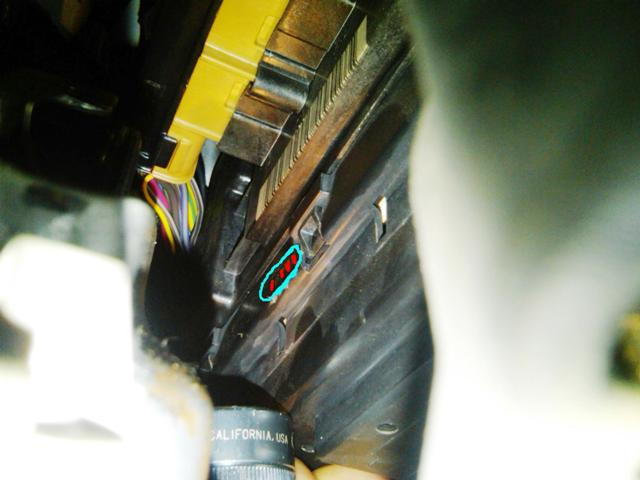
Disconnect the harness locator at the front of the SJB.
Remove the 2 screws and the steering column cover panel.
CAUTION: Secure the steering wheel to prevent damage to the clock spring assembly.
Remove the shaft-to-steering column bolt and separate the steering column shaft from the steering column.
Remove the 2 bolts and position the parking brake release handle aside.
Remove the LH A-pillar trim panel. For additional information, refer to Section 501-05 .
Remove the LH cowl side trim panel. For additional information, refer to Section 501-05 .
Position the LH door weather seal aside.
Remove the LH instrument panel side finish panel.
CAUTION: The bulkhead electrical connector is lever assisted. Do not damage the lever when releasing the electrical connector.
Disconnect the LH instrument panel bulkhead connector.
Remove the driver side vent assembly.
Remove the headlamp switch assembly. For additional information, refer to Section 417-01 .
Remove the 3 SJB mount screws and release the SJB from its locators.
Remove the 2 LH instrument panel side mount bolts.
CAUTION: The SJB electrical connectors are lever assisted. Do not damage the lever when releasing the electrical connectors.
Disconnect the 5 SJB electrical connectors and remove the SJB.
Disconnect the remote keyless entry (RKE) antenna.