410Custom's builds a 2007 Ranger V8 - custom truck build - Project "Ranger Premier" | Page 28 | Ford Explorer Forums - Serious Explorations

  • Register Today It's free!

410Custom's builds a 2007 Ranger V8 - custom truck build - Project "Ranger Premier"

okay so first up I need to convert the Holley injector harness to use the 98+ style connectors.
Every wire will be soldered on this harness
harness will be tailored to fit the engine bay
holley connectors are removed and factory 5.0 connectors are installed

image_19.jpg


image_17.jpg


image_8cc.jpg


Holley main harness test fit / installed up the spine of the transmission and into the cab of the truck
Fuel injection harness final wrapped and installed
Crankshaft and Camshaft sensor harness also installed

These are 98-01 style 5.0 injectors, 19# along with the returnless style fuel rail. This will work well with our 07 Ranger style fuel system

image_0003.jpg


crank and cam 5.0 sensors along with their appropriate pigtails.
Wired per Holley chart (and my notes like these)


Now it is time to wire in the Ignition (coil pack) wires. They get integrated into the Holley main harness

per the chart from earlier

image_2bb.jpg


image_4bb.jpg


These wires get pinned into the Holley PCM connector P1B here
image_5bb.jpg


Pull out the white plastic spacers, and add the wires to designated pin locations per chart.
Also you must release the white lock, this will allow pins to slide in and out of connector
image_8bb.jpg


press here
image_9cc.jpg

unlocked


image_7bb.jpg


Ignition coil driver wires going in pins 15-17 and 21-24
Pin 14 is ground distribution from PCM, three wires get combined here
imageaa.jpg


image_1aa.jpg


All wires added now, grounds combined
Coil pack wiring integrated!
image_2aa.jpg


Now main harness can be installed back into the truck for final time. It slides right in on the passenger side above the header and behind the trans dipstick

image_7aa.jpg


wiring laid out over engine, time to clean a bunch of 5.0 parts

image_8bb.jpg image_3bb.jpg


Join the Elite Explorers for $20 each year.
Elite Explorer members see no advertisements, no banner ads, no double underlined links,.
Add an avatar, upload photo attachments, and more!
.


Is that the Holley Terminator Max kit part # 550-943?
Also are you changing the injector connectors because you are using the 98-01 injectors?


image_3aa.jpg


image_4aa.jpg


image_5aa.jpg


Next line of parts being prepped
image_6aa.jpg


meanwhile I need to sort out the power steering line and fuel lines

EGR is being deleted, however I still need a vacuum feed for the fuel damper. Modified factory parts work perfectly here
image_5dd.jpg

Here is where the injector and cam/crank sensor harness plug in
image_2dd.jpg

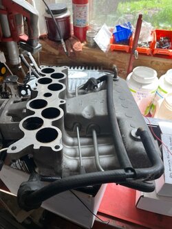
Test fitting the intake plenum and spacer

image_8dd.jpg


image_7dd.jpg


more details from the cam and crank sensor wiring harness from earlier

camcrank.jpg

image_1ee.jpg


image_4ee.jpg


image_6ee.jpg
image_5cc.jpg


Very nice. I like wiring when it's all clean and routed OEM style.

Does that Holley EFI have the ability to run COP ignition, or what's the cost difference in models? I'm considering the COP version for my boosted application, but I don't know if the coils can fit on the valve covers.


yes 07 Ranger is returnless fuel so I am using 98-01 style injectors and rail

Yes the Holley can run a COP ignition, the cost difference is marginal on the Holley side of things. I am actually using the COP ignition harness modified to use the Ford coil packs, by way of the coil drivers

When I build my truck with a similar system I will likely use the LS style coils with COP ignition


Excellent, then I can get you to show the way. Will the Holley control module fit in the firewall by chance, or does it have to go inside?


The Holley PCM can be mounted under the hood, there are some precautions to take
It should not be exposed to the elements directly, I was tempted to mount it in the stock 07 location which is in the firewall and exposed to the elements! It can get wet but they want you to angle it down so the connectors drop water off.. this would not work for me I wanted to put it under the hood in the stock location but mount it so you could see the lights… wiring this would be very difficult
later I decided the center console or under the dash is its natural home, the 2007 Ranger has way different holes in the firewall, not like the 95-04 trucks I am used to........

I have spent much time with the Holley system trying different routing.
I have left the map and knock sensor plugs in place in an effort to leave things stock(ish)
It could be further streamlined by removing un used connectors
Who knows what kind of mods may come in the future.

I still have more to cover working through these pictures
The fuel line has been sorted out, and I believe I have a power steering line that will work , again the 07 is different then the earlier Rangers/Tracs
The IAC, TPS, CTS, and IAT sensors will be wired when the intake is installed.
I have a plug for the Torque Monster EGR bung on the way. It is a 22mm 1.25 pitch stainless drain plug
The hole in the intake plenum will get a simple block off plate.

All parts are cleaned, some are being painted. I have everything I need to complete the engine
Working through small things like oil pressure, fuel pressure and trans line pressure port locations is also happening.
Once the engine bay is complete the real wiring will begin, the truck side of things.
I have many electronics to install, enough to warrant the addition of a fuse/relay box of some sort

accessory brackets going in, needed to test fit PS pump to sort out the high pressure line

You can see the Holley coil drivers we will be using to emulate the stock DIS, waste spark, coil pack ignition
These may very well end up being mounted on the underside of the coil tower tripod

image_4ff.jpg


image_3ff.jpg


image_5ff.jpg


Heater bypass hose installed, these are "cut to fit" these days, here is how I do it for a perfect fit

image_1ff.jpg

image_2ff.jpg


trace the factory hose, makes perfect replica, trim in correct spots.
I use vaseline inside the hose on both ends, put it half way on thermostat housing, half way on water pump and then press.... can even be done in the truck this way on the side of the highway, covered in coolant..... don't ask! Any long time 5.0 owner knows what I mean


Running wires like the factory is hard ....I know
Great work looking great

Don't burn off your ring finger because of the ring

I remove mine or tape over it


So far I still have my ring and my finger!! I will be careful though I have heard the horror stories


here we can see the holley wiring has made its way into the cab! (Cab floor needs a cleaning Yes I see that too!)
holleyin-.jpg


now to sort out some of the hurdles. I had to figure out a fuel line and power steering high pressure hose solution. The 07 Ranger is different from the earlier trucks, the stock fuel line runs up the spine of the v6 transmission. The high pressure PS hose also mounts to the track differently.
I found a 02-05 4.0 power steering line is able to be made to work.

image_111.jpg


image_311.jpg

PS line will need some bending to be perfect, but it works
image_511.jpg


image_411.jpg


has a funky bend in it, could have a custom line made if needed by modding this one, but lets see if we can make this one work even with its funky routing. I have a large line bender that really helped to shape it
image_911.jpg


image_811.jpg


PS line sorted!!

The fuel line I snagged from a 02 sport trac, plugs into the 5.0 and plugs into the 07 style fuel filter.

Time for some routing and under hood mods, lets get this 5.0 put together!
image_2nn.jpg


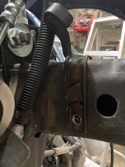
the stock 5.0 starter/ ground/charging harness has this metal bracket that ties into the explorer frame. It keeps the wire loom away from the oil filter and fan, so we will re use it. To make it fit the ranger frame better I cut it up a little bit, drilled a pilot hole and mounted it with a self tapping screw. here you can see I am using a C clamp so I can bend the tangs and free its grip from the wire loom

Install the top "tab" the ranger frame has a spot for it, then mark the hole on the bottom where to drill (oval mark)

image_6nn.jpg


image_31212121.jpg

arm cut off, hole drilled


While we have the grinder out mine as well take care of two more brackets
image_3nn.jpg


When running a 1" intake spacer the coil tower and throttle cable holder need some mods. Basically cut off some bits
image_4nn.jpg


parts removed, let the mods begin!
image_5nn.jpg

All parts sent off to the parts washing department (me)

Wiring bracket final install
image.jpg

image_88766767.jpg


Everything is cleaned and prepped before install, need to find a home for the coil drivers
image_1121.jpg

image_22122.jpg


Meanwhile, remember this little gem? I dug the cv axle out so I can ship it to RCV for repair...... fingers crossed image_244.jpg


image_7nn.jpg


Next items to be wired to the Holley harness, IAC, TPS, CTS, and coil packs. Factory 5.0 pigtails soldered to Holley wires, wires cut to fit my under hood routing.

image_56566565.jpg


Holley oil pressure sender installed to the 5.0, just then I realized I will need two oil pressure sensors, one for the stock dash also. So I ordered a dual mount for a 302 from Ebay, $30
image_4fggfdgfdfg.jpg

Once it arrives I can install both sensors

image.jpg

Messing around with fuel lines, somehow I ended up with two 06-11 Ranger lines? I also tried a 05 ranger line, it would have needed an adapter, then finally I found the 02 sport trac line will be plug and play. Had to swap the heat shield also on the ranger frame...they are different in 06+ more on that later

image_778676876.jpg


my neighbor has been down here last few days too, his 19 year old just graduated high school, he has a 95 S10 that blew up its engine. Together we have been prepping this new 04 Vortec 4.3 to go in. Yes Chevy stuff too......04 vortec engine required a edelbrock intake for a carb, then a carb to TBI adapter


View attachment 430531

Next items to be wired to the Holley harness, IAC, TPS, CTS, and coil packs. Factory 5.0 pigtails soldered to Holley wires, wires cut to fit my under hood routing.

View attachment 430532

Holley oil pressure sender installed to the 5.0, just then I realized I will need two oil pressure sensors, one for the stock dash also. So I ordered a dual mount for a 302 from Ebay, $30
View attachment 430533
Once it arrives I can install both sensors

View attachment 430534
Messing around with fuel lines, somehow I ended up with two 06-11 Ranger lines? I also tried a 05 ranger line, it would have needed an adapter, then finally I found the 02 sport trac line will be plug and play. Had to swap the heat shield also on the ranger frame...they are different in 06+ more on that later

View attachment 430535

my neighbor has been down here last few days too, his 19 year old just graduated high school, he has a 95 S10 that blew up its engine. Together we have been prepping this new 04 Vortec 4.3 to go in. Yes Chevy stuff too......
04 vortec 4.3 required aftermarket intake to allow a carb to go on, then a carb to tbi adapter so we can run the factory 95 fuel injection.
After watching this S10 fiasco I will stick with my Rangers thank you very much

image_711.jpg


factory heater hose manifold cleaned and painted, ready for install. Also can see the 02-05 style fuel line heat shield


final routing for the crank and cam sensor wires
image_533.jpg

behind the heater hoses lol

image_333.jpg


heater manifold installed to engine
image_233.jpg


I'm liking this location for the Holley 4 channel coil drivers, make it so


image_733.jpg


You can see the Holley coil pack (ignition) wiring has been routed down the drivers valve cover, wrapped and loomed.
Heater manifold and hoses installed. The fuel injector harness was final wrapped and installed. Cam and crank sensor wires routed...this engine bay is ready to go together!!

test fitting the upper plenum, getting some measurements for possible COP/ LS coil install
image_833.jpg


2.5" clear under plenum on drivers side, this is with the 1" intake spacer
image_933.jpg


tons of space on the passenger side
image_3vv.jpg

3.5" vertical clear at top of valve cover
5.5" at the bottom
image_4vv.jpg


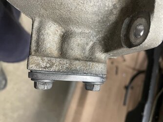
Now I need a EGR block off plate for the back of the intake plenum/elbow. Time to fabricate!

image_133.jpg

Gasket is traced onto 1/4" plate
image33.jpg

image_655.jpg


band saw and grinder, then a hand file and BLAMO
EGR block off, oh yeah I cut a new gasket too
image_422.jpg


image_522.jpg


image_422.jpg image_322.jpg

Speaking of plugging up the EGR
the new Drain plug / TMH EGR bung plug arrived today
stainless 22mm 1.25 pitch drain plug with gasket
Will get some anti seize and final install. I ordered two, I am sure I will need another one of these!

image_6vv.jpg


image_7vv.jpg


Before the intake goes on the engine ground strap is added
image_255.jpg

image_355.jpg


nice work jamie. once again, thanks for posting everything you have put up. im also still trying to figure out a good place for the coil drivers. im trying to figure out in my head if they will fit on the back of the glove box, the route the wires somehow, or stuff them under the console. will have to look more into that when i lay the other part of the harness in. i have noticed you are also using the ford temp sensors as well.
was going to suggest using steel braided fuel line to make it easier to put in, but you have it handled.
i did want to ask however, for your wire harness coming up in the trans tunnel. have you modified the pinch weld so it wont rub on it, or have you tied it to the vent tube? im not sure if i am going to bend the pinch weld and have it hug the floor pan, or try to float it above the trans.


Some wiring
the routing and length is sorted for the TPS, CTS, and MAT (manifold temp for holley, we call it IAT, intake air temp)
Now soldered

image_2vv.jpg


Built a simple mount for the two 4 channel coil drivers, really happy with how this turned out
image_755.jpg


image_855.jpg


test fit / perfect!!

image_955.jpg


image_1055.jpg


coildrivehome.jpg


image_222.jpg


Alternator wiring, AC line routing being sorted, most things are just like a factory 5.0
Our owner really likes a stock ish under hood engine bay
This one is clean and well sorted
I have plans for the upper intake paint job :) Shhhhhhh

image_8vv.jpg


Each coil driver needs a ground directly to the corresponding head.
These coil tower, lower intake bolts go directly into each head.
Perfect
image_155.jpg


final paint
image_722.jpg

image_822.jpg


I changed up the vacuum line a little bit for the back of the intake. Now it has two feeds, one for the fuel rail damper and the second will be for the Holley PCM built in MAP sensor


How about this color, Jon did this one ages ago for another member. I like that shade, it's similar to a titanium color.


Explorer intake 02.jpg


@410Fortune I just saw tonight where Wednesday you measured and posted the space between the valve covers and intake. Thanks. I also re-read the electrical/wiring part so that I would quit asking so many questions. One question though, with the CNP smart coils are the coil drivers required?


dang good question!! I do not think so not with COP, but we need to ask Holley that question to make sure.

It goes deeper then this as well, since the Ford ignition is waste spark and only uses 4 coils....... I am wondering if I can combine cylinders BEFORE the coil driver and then just use ONE 4 channel coil driver instead of two.....
This is how we learn! By doing.

I have about 30 more pictures to post, will get some time for another big update today/tomorrow


coil drivers ARE needed for CNP or COP ignition, I confirmed w Brett

more on wiring the waste spark ignition and mounting of the coil drivers. I am very happy with how this turned out!

image_14.jpg


bracket back from final paint shop (me), here you can see how the holley ignition harness is routed along drivers side injectors and to the back of the coil tower

image_24.jpg


the TMH, EGR block off plug is installed fully, anti seize on the threads. This is a 22mm 1.5 pitch drain plug (not 1.25 like I said earlier)

Now before I cut the Holley plugs off the coil drivers on the coil pack side of things I needed to carefully mark the wires with their corresponding pin letters, as you can see all of the wires are black, so this is very important to get it right. I triple checked before I cut a wire. The connectors are labeled very faintly with letters. I used a black marker and wiped it off on the white plugs, so I could see the letters clearly. On the black plugs I could not do so, so I used tape


image_34.jpg


On the output side of things (coil pack side) wires A-D are the coil driver wires (signal) and wires E-H are the red power to coil wires, all 4 wires E-H are the same, basically switched power to coil. I only need one red wire on each coil pack, for good measure I used two and capped the other two off
image_74.jpg

image_44.jpg


Coil drivers marked, one feeds cyl 1-4 and the other 5-8< DO NOT MIX THEM UP!!!!! Very important that cyl #1 wire leaves PCM, goes through coil driver, and ends up at Cyl 1 coil..... same is true for cyl 2-7. This wiring was done very carefully, checked several times along the way before final wrap!!
image_54.jpg


At the end of the day (or ignition coil harness) we only have 6 wires
Why? Because the Ford waste spark only uses 4 coils.

The chart I made earlier shows this very clearly, ALSO the PDF file WILL BE updated, earlier I had the wires labeled wrong!!
I am working on updating it today (06/20)

image_84.jpg


here you can see two coil signal wires come together to feed a single coil.
Wiring is done per the PDF chart I posted earlier, MUST BE DONE PERFECTLY!!!!!! or you can destroy your engine (not likely) but Holley makes it very clear you must have a professional (like me) install this system. A full understanding of why this is wired the way it is is needed, do not just copycat something you see on the net, you need to know the ifs, whys and butts of this wiring. Your harness may use different pin locations or wire colors! Mine is a Holley kit made for the Ford 302 and 4r70w, the injector harness and main harness match up. Then I custom wired the GM coil on plug ignition harness to be a Ford waste spark ignition. CAREFUL folks.


Join the Elite Explorers for $20 each year.
Elite Explorer members see no advertisements, no banner ads, no double underlined links,.
Add an avatar, upload photo attachments, and more!
.


Dang it I tried to post way more then this but had forum issues this am sob I will try again later


Back
Top