- Joined
- February 8, 2003
- Messages
- 9,824
- Reaction score
- 84
- City, State
- Sacramento, CA 95827
- Year, Model & Trim Level
- 1992 XLT
Well it has been a long journey but now comes the final little bit of building this transmission... putting all the component parts together. It has been frustrating, interesting and rewarding.
Just like the first time I built an A4LD, I have had these guts in and out of the case several times. Sometimes because I screwed something up, somtimes because I wasn't entirely sure of what I was doing or had done....and sometimes because I forgot to take a picture.
I like to take lots of pictures so people following in my footsteps have something to reference. I believe they are helpful.. I hope you agree - they are huge time consumers to take, edit and post!
Let's get to the task at hand.
The case has been prepared as in the initial post of this Diary. I like to use vaseline as sort of an "assembly lube", so I will lube the rear case bushing...

The output shaft has had solid teflon seals added for the direct drum, and I let the seals rest for a few days inside the drum to better "size" up. You may remember how sloppy loose they were when we first put them on.... look at them now! I strongly believe in using solid rings here as the direct drum is a common failure point in this transmission and these help prevent that failure!

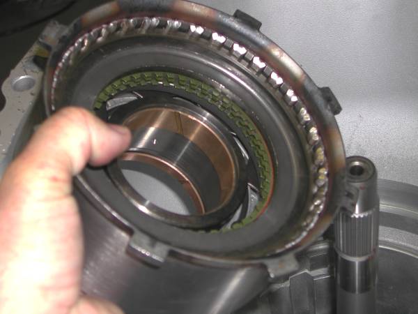
I pulled the direct drum off and reassembled the ring gear onto the output shaft to once again make it a single assembly. Next I lubed the steel sealing rings that will ride in the newly steel bushed case rear bore....

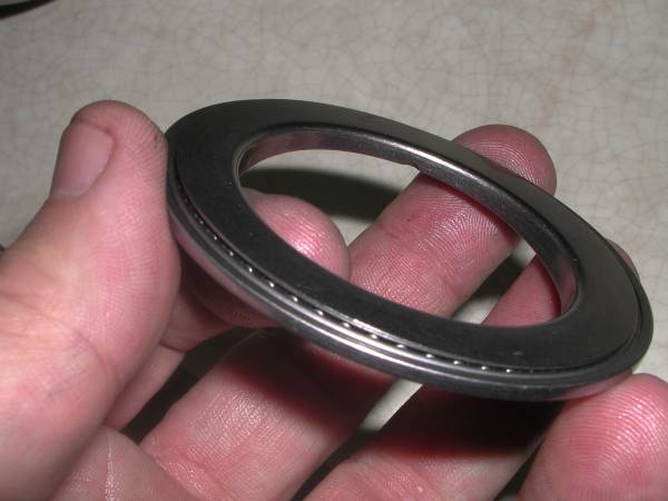
I also added the 1st Torrington to the rear of the case - the output shaft hub rides on this. Here it is... notice the lip that surroungs it and holds it in place?

And here it is installed in the case

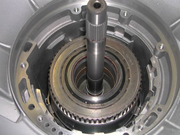
I found out that installing the output shaft/hub assembly is not all that easy. I broke a couple steel rings by being too rough. Those rings are kind of like glass. You need to put one hand under the output shaft as you install it and lower it gently into the bore and wiggle it a lot as you rotate it. It WILL drop into place, gently. (This was the first of many surprises).
Here it is all installed. I was so busy being careful I did not get pics of the process itself, but you get the idea...

The direct drum uses the second of the multiple torringtons in this transmission. We practically have a torrington on top of a torrington - sandwiching the ring gear hub. Here it is:
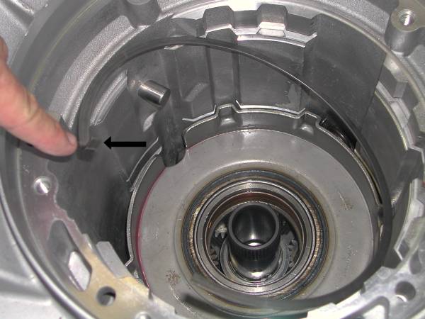
It goes onto the back of the direct drum, as shown here by the arrow

Notice the wad of vaseline used to help hold it in place. I will repeat, make sure your hub is all installed in the drum plates correctly before inserting the direct drum. It is all but impossible to get the hub back in later (if the need arises) with the direct drum in place inside the ring gear! Anyway here it is all installed:

Notice that the top edge of the ring gear is below the "ledge" in the case. If it isn't it is not all the way installed - probably hanging up on a steel seal in the rear case bore. (First of many check and recheck things)
That hub in the direct drum connects to the planetary. The planetary has a splined end that connects into the hub (everytime I took the planetary out it pulled out the hub, making life miserable... plan carefully so you DO NOT have to remove the planetary!) I would note that since all my internals are BRAND new, the fit is rather tight and precise.. on a worn transmission I am sure most of this would easily go back together! That was one of my biggest headaches!
Ok next up for installation is the reverse band. Right under it is a "snap ring" sort of appearing ring that FORD calls a retaining ring. I am uncertain of any real function other than as an assembly aid to support the reverse band. But, don't forget to install it in the case.
There are two steel pins in the case that the reverse band rides against, and then the servo pin serves to hold it in place on the other side. Here it is, pre-soaked in ATF

and in the case

The arrrow points to the case anchor pins.
Once the band is on the two pins, piut the servo in place to capture the other end...

Make sure it is in the hole on the band where it belongs.
I discovered two things during my assembly. First, put the band in before the planetary. Second put the planetary (center) support into the planetary first and install them as a unit. THERE, I just saved you all an hour or more or trial and error! Grrr. I made both mistakes.
Next comes the planetary and the support. Here is the planetary:

and here is the support

The support goes into the roller one-way clutch, and you install it as you rotate it counterclockwise - so when you are done it holds in the clockwise direction and freewheels in the counterclockwise!! THIS IS IMPORTANT!
Here they are together. The cutout allows you to install it past the OD band pin in the case:

Once you have them together lower them into place ... this pic is a little out of sequence since I had installed the sun gear and the anti clunk spring, but you get the idea..

The next step is to install the anti-clunk spring. I did not find good info on exactly how to do that and after much trial and error more or less intuitively did it. Here is that spring (If I find out I did it wrong you will hear me screaming from the next state)
(pic coming)
With this in place we can install the support support snap ring.... it has an upturned end (arrow)
It fits deep into the retaining groove. Try and position it so the upturned end is in a narrow groove in the case so it won't be "walking around".


With this installed, we can put in the sun gear and the torrington that goes on it (#3 - arrow)

and we install it

This part will spline into the forward clutch plate hub.
Ok now there is a bit of a dilemma. Many experts say to assemble the remaining components as an assembly and install them that way. The resulting part is heavy and difficult to handle. Some even make slings to lower them into the case.
I evaluated everything many times and came to the conclusion I would try it piece by piece. It worked, and I for one feel better seeing everything going in orderly.
SO... that said, here is the next part.. the sun shell. The end of the gear rides on the torrington on the sun gear. ( I always like to ask myself what is providing the bearing surface on each part so I won't forget anything)

Here it is installed:

Notice the sun gear shaft stub sticking up in the middle. (That splines into the forward hub, as noted)
There is a need for another torrington (by our method of counting them - #4) in this location. It looks like this.... with little protrusions to hold it centered

here it is installed

On this rides the forward clutch plate hub. But inside the HUB is another torrington (our #5 - the FORD manual numbers them differently). That one looks like this, and can only go in correctly one way... you will know what that is when you install it. Here is the torrington:

and here it is nestled itno the hub spot for it

Before we install this though, we need to use the stub staft. (How would you like THAT name?) That slides easily into the direct drum and couples it to the forward drum....

Notice I am using the latest version! It slides right in

Leaving us looking like this at this point

(starting to get busy at this point in the tranny operation - lots going on in this section of the transmission) Next we add the forward hub.... I made sure the hub was aligned in the forward clutch plates before I carefully removed it... hoping to easily slide the forward clutch back onto it - you will understand this once you try it.... and, it worked! Anyway I am ahead of myself, here is the hub

and on that sits - the forward clutch!

Time for the last major piece of internal hadware - the reverse clutch. Here it is... 3 plates....
And it also has a torrington (Our #6)... much like the rear case one with a lip around it:

It goes here on the reverse clutch drum

here it is installed

If you cannot get it to stay in place with vaseline, you can place it upside down into the snout of the forward clutch and that will work just fine.
The reverse drum needs to at the same time spline onto the forward clutch, and also the dog ears need to nestle into the grooves on the shell... I was worried this might be tough to accomplish, but it wasn't. The dog ears will ride in the shell about mid point - I was expecting them to bottom, but then I looked as used shells. They do not bottom. Here is the reverse drum and mechanical diode on it, installed...
Next in this thread is the OD band installation.. It is soaking as we speak. NON - KEVLAR. Stay tuned.
Just like the first time I built an A4LD, I have had these guts in and out of the case several times. Sometimes because I screwed something up, somtimes because I wasn't entirely sure of what I was doing or had done....and sometimes because I forgot to take a picture.
I like to take lots of pictures so people following in my footsteps have something to reference. I believe they are helpful.. I hope you agree - they are huge time consumers to take, edit and post!
Let's get to the task at hand.
The case has been prepared as in the initial post of this Diary. I like to use vaseline as sort of an "assembly lube", so I will lube the rear case bushing...
The output shaft has had solid teflon seals added for the direct drum, and I let the seals rest for a few days inside the drum to better "size" up. You may remember how sloppy loose they were when we first put them on.... look at them now! I strongly believe in using solid rings here as the direct drum is a common failure point in this transmission and these help prevent that failure!
I pulled the direct drum off and reassembled the ring gear onto the output shaft to once again make it a single assembly. Next I lubed the steel sealing rings that will ride in the newly steel bushed case rear bore....
I also added the 1st Torrington to the rear of the case - the output shaft hub rides on this. Here it is... notice the lip that surroungs it and holds it in place?
And here it is installed in the case
I found out that installing the output shaft/hub assembly is not all that easy. I broke a couple steel rings by being too rough. Those rings are kind of like glass. You need to put one hand under the output shaft as you install it and lower it gently into the bore and wiggle it a lot as you rotate it. It WILL drop into place, gently. (This was the first of many surprises).
Here it is all installed. I was so busy being careful I did not get pics of the process itself, but you get the idea...
The direct drum uses the second of the multiple torringtons in this transmission. We practically have a torrington on top of a torrington - sandwiching the ring gear hub. Here it is:
It goes onto the back of the direct drum, as shown here by the arrow
Notice the wad of vaseline used to help hold it in place. I will repeat, make sure your hub is all installed in the drum plates correctly before inserting the direct drum. It is all but impossible to get the hub back in later (if the need arises) with the direct drum in place inside the ring gear! Anyway here it is all installed:
Notice that the top edge of the ring gear is below the "ledge" in the case. If it isn't it is not all the way installed - probably hanging up on a steel seal in the rear case bore. (First of many check and recheck things)
That hub in the direct drum connects to the planetary. The planetary has a splined end that connects into the hub (everytime I took the planetary out it pulled out the hub, making life miserable... plan carefully so you DO NOT have to remove the planetary!) I would note that since all my internals are BRAND new, the fit is rather tight and precise.. on a worn transmission I am sure most of this would easily go back together! That was one of my biggest headaches!
Ok next up for installation is the reverse band. Right under it is a "snap ring" sort of appearing ring that FORD calls a retaining ring. I am uncertain of any real function other than as an assembly aid to support the reverse band. But, don't forget to install it in the case.
There are two steel pins in the case that the reverse band rides against, and then the servo pin serves to hold it in place on the other side. Here it is, pre-soaked in ATF
and in the case
The arrrow points to the case anchor pins.
Once the band is on the two pins, piut the servo in place to capture the other end...
Make sure it is in the hole on the band where it belongs.
I discovered two things during my assembly. First, put the band in before the planetary. Second put the planetary (center) support into the planetary first and install them as a unit. THERE, I just saved you all an hour or more or trial and error! Grrr. I made both mistakes.
Next comes the planetary and the support. Here is the planetary:
and here is the support
The support goes into the roller one-way clutch, and you install it as you rotate it counterclockwise - so when you are done it holds in the clockwise direction and freewheels in the counterclockwise!! THIS IS IMPORTANT!
Here they are together. The cutout allows you to install it past the OD band pin in the case:
Once you have them together lower them into place ... this pic is a little out of sequence since I had installed the sun gear and the anti clunk spring, but you get the idea..
The next step is to install the anti-clunk spring. I did not find good info on exactly how to do that and after much trial and error more or less intuitively did it. Here is that spring (If I find out I did it wrong you will hear me screaming from the next state)
(pic coming)
With this in place we can install the support support snap ring.... it has an upturned end (arrow)
It fits deep into the retaining groove. Try and position it so the upturned end is in a narrow groove in the case so it won't be "walking around".
With this installed, we can put in the sun gear and the torrington that goes on it (#3 - arrow)
and we install it
This part will spline into the forward clutch plate hub.
Ok now there is a bit of a dilemma. Many experts say to assemble the remaining components as an assembly and install them that way. The resulting part is heavy and difficult to handle. Some even make slings to lower them into the case.
I evaluated everything many times and came to the conclusion I would try it piece by piece. It worked, and I for one feel better seeing everything going in orderly.
SO... that said, here is the next part.. the sun shell. The end of the gear rides on the torrington on the sun gear. ( I always like to ask myself what is providing the bearing surface on each part so I won't forget anything)
Here it is installed:
Notice the sun gear shaft stub sticking up in the middle. (That splines into the forward hub, as noted)
There is a need for another torrington (by our method of counting them - #4) in this location. It looks like this.... with little protrusions to hold it centered
here it is installed
On this rides the forward clutch plate hub. But inside the HUB is another torrington (our #5 - the FORD manual numbers them differently). That one looks like this, and can only go in correctly one way... you will know what that is when you install it. Here is the torrington:
and here it is nestled itno the hub spot for it
Before we install this though, we need to use the stub staft. (How would you like THAT name?) That slides easily into the direct drum and couples it to the forward drum....
Notice I am using the latest version! It slides right in
Leaving us looking like this at this point
(starting to get busy at this point in the tranny operation - lots going on in this section of the transmission) Next we add the forward hub.... I made sure the hub was aligned in the forward clutch plates before I carefully removed it... hoping to easily slide the forward clutch back onto it - you will understand this once you try it.... and, it worked! Anyway I am ahead of myself, here is the hub
and on that sits - the forward clutch!
Time for the last major piece of internal hadware - the reverse clutch. Here it is... 3 plates....
And it also has a torrington (Our #6)... much like the rear case one with a lip around it:
It goes here on the reverse clutch drum
here it is installed
If you cannot get it to stay in place with vaseline, you can place it upside down into the snout of the forward clutch and that will work just fine.
The reverse drum needs to at the same time spline onto the forward clutch, and also the dog ears need to nestle into the grooves on the shell... I was worried this might be tough to accomplish, but it wasn't. The dog ears will ride in the shell about mid point - I was expecting them to bottom, but then I looked as used shells. They do not bottom. Here is the reverse drum and mechanical diode on it, installed...
Next in this thread is the OD band installation.. It is soaking as we speak. NON - KEVLAR. Stay tuned.