96 Explorer ABS Code C1194 | Ford Explorer Forums - Serious Explorations

  • Register Today It's free!

96 Explorer ABS Code C1194

kjtooltime

New Member
Joined
September 29, 2010
Messages
4
Reaction score
0
City, State
Oceanside, Ca
Year, Model & Trim Level
1996 XLT 5.0L
Hi All,

I have a 1996 Explorer with a V8 and 4 wheel disk that has an ABS light that stays on all the time (with Key on only or if the engine is running and vehicle moving).

Using a scan tool, I was able to pull ABS Code C1194 (ABS outlet valve coil LF Circuit Failure). From the research that I did, it seemed to point to the ABS Module. I replaced the module (located in the left fender next to the battery) and the light is still on.

I have also checked the continuity of all the sensors.

What else could be the problem?

Does a new ABS module have to be programmed?

Any help would be greatly appreciated.

Thanks!


Join the Elite Explorers for $20 each year.
Elite Explorer members see no advertisements, no banner ads, no double underlined links,.
Add an avatar, upload photo attachments, and more!
.


If you replaced the abs module, then the HCU or hydraulic control unit would be the problem.


Swetrid, thanks for your reply.

I found a wiring diagram for the ABS system so this weekend I checked the resistance at the connector to the ABS module of all the sensors and valves of the HCU. I found the Left front dump vale around 6 Meg ohms while the rest of the valves of the HCU were around 10 ohms. So it is a bad HCU. I wish I would have taken this approach instead of blindly ordering the module. Off to ebay to hopefully find a good HCU.


Hi,

This is the HCU?

Cannot be repaired?

absy.jpg


Thanks


Hi Orleans,

Yeah that is the picture of the ABS pump (HCU). I'm sure they are rebuildable since I have seen them at Kragen for around $350. I have not taken one apart but I would like to see what is inside one.

I'm waiting for the one I ordered off ebay. Hopefully it is a good ABS pump.


Hi,

Please post the result.

My research appears the module, but I'd rather not risk it. I also have the code C1194


Thanks


I bought an ABS pump off ebay and that fixed the problem. I plugged in the two connectors of the new pump (before hooking up the hydraulic lines) and the light went out. I wanted to make sure this fixed the problem before swapping pumps.

To check the new pump, one connector has two wires and go to the pump motor. The resistance is around 0.5 ohms (can be checked by placing the ohm meter acrossed each wire connector). The second connector has 8 wires. All the wires are the same color so you have to look at the harness that plugs into the plug to find the Orange with Yellow stripe (there are two wires like this and either one can be used, that leaves 6 other wires to be checked). Now place one ohm meter lead where the Org/yel wire would make contact and measure each other wire that has the same color. You should see about 5 -10 ohms for the six valves inside the ABS pump. I had one of my valves show an open.

If the ABS pump shows good, then it will be either the harness from the ABS pump to the ABS module or the ABS Module is bad.

Hope this helps other with troubleshooting this problem.


Old thread... but it's helped me out greatly on my 97 XLT: many thanks to kjtooltime!!!

I am dealing with the C1194 code at the moment, and based on the above information and my testing, it's clear that my Left Front Dump Valve is acting up—ohm reading is WAY out of spec. (Not surprising given the age of the unit and the state of the fluid: nasty.)

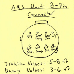
In case it's helpful to others, I'm attaching a quick diagram of the 8-pin ABS Hydraulic Control Unit connector (looking at the part side of the connector, which has all light blue wires). I've double-checked the pin assignments and specs from the service manual, and it's basically a simple resistance test with a multimeter, between one of the upper left or right pins (those correspond to orange/yellow wires on the harness side) and each of the six valve pins, one at a time. This test could be done pretty easily at a JY, before you even purchase a replacement unit, if you go that route.

Resistance Specs
Isolation Valves: 5-8 ohms
Dump Valves: 3-6 ohms

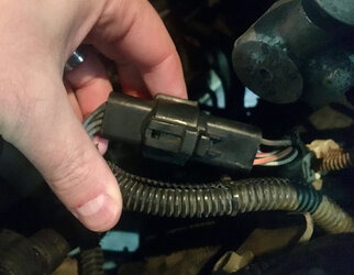
ford-abs-pump-connector-diag.jpg abs-8-pin-connector.jpeg abs-unit-label.jpeg


Something else to keep in mind is that some set codes do not just go away when you replace the faulty module, instead need a scan tool to clear them. Maybe enough driving would also do that, I never had the patience to wait and see after a repair (attempt) instead of clearing a code then seeing if it comes back.


Fortunately, C1194 does go out, once you replace the Hydraulic Control Unit, like kjtooltime mentioned back in 2010. I spent a big chunk of Saturday, trudging all over the local yard, looking for the cleanest HCU I could find in a similar year Explorer/Mountaineer. Being able to test the isolation and dump valve resistances on-site was very helpful in terms of identifying one that "should" work. Once I plugged the unit into my rig, the light was G-O-N-E. (Before I did any of this, I flushed all the old, filthy brake fluid out of the vehicle and replaced with new—didn't want to deal with all of this again, a week later, if I didn't have to...)

But... nothing has been said in this thread yet about how to bleed the HCU, once you replace it, since a standard brake-bleed won't necessarily deal with air in the HCU's valve body. Most of you probably know there's a special dealer tool that automates the process (some scan tools are able to do it, as well), but I was looking for a basic, DIY-friendly method. I started by doing a good bit of research on the "Teves Mark IV ABS System" and then came across a thread on the SCCOA forum that pretty much nailed it. So, here's what I landed on to bleed the whole system, after installing the replacement unit:
  1. Do a standard brake bleed: RR, LR, RF, LF
  2. Do the HCU bleed process (see below)
  3. Do a final standard brake bleed: RR, LR, RF, LF
HCU Brake Bleed
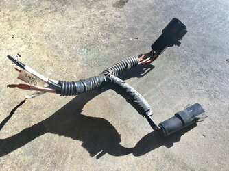
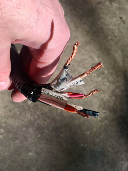
  1. Unplug the replacement HCU's 2-wire motor connector and 8-wire valve connector from your vehicle's harness. Take the old wiring harness from the donor vehicle (yes, you need to cut the whole thing off at the JY and bring it home!) and strip about 3/4" off the end of each wire. Twist the two orange/yellow-stripe wires together (positive connection for all valves), twist the three small dump-valve ground wires together (orange, pink, and tan/red), and then identify the two large ABS pump motor wires: tan/red for positive and black for negative. You won't use the other wires; tape 'em off. Connect this "pigtail" to your HCU.
  2. Your (fully-charged) auto battery will be used to power everything. First, completely disconnect your battery from the vehicle and then, using a set of jumper cables or similar, connect the large black pump motor wire and the three dump-valve ground wires to battery negative.
  3. When you are good-and-ready and have rehearsed this a few times, start a 60-sec timer and immediately connect the large tan/red pump motor wire to battery positive. The ABS pump will begin running and building pressure.
  4. When 20 seconds have elapsed, and with the pump motor still running, connect the orange/yellow wires to battery positive to open the dump valves and hold in place for 20 seconds, then remove.
  5. Let the ABS pump motor continue to run for 20 seconds longer and then disconnect everything from battery. (Total run time for everything: 60 seconds.)
  6. Disconnect your makeshift pigtail and reconnect your vehicle's harness to the HCU. Reconnect your battery cables, and HCU bleed is complete.
abs-hcu-pigtail.jpeg abs-hcu-pigtail-cu.jpeg
 

Attachments

  • 97-exploreer-abs-wiring-EVN04202.pdf
    25.4 KB · Views: 91


Back
Top