How to: - A4LD DIARY - PT 2 | Page 2 | Ford Explorer Forums - Serious Explorations

  • Register Today It's free!

How to: A4LD DIARY - PT 2

Prefix for threads which are instructional.
Awwww, please ? <g> Thanks for the help. I still think that since both the old plates and the new spiral groove plates are the same thickness, I am staying with the number in the A4LD. I do appreciate the feedback.


Join the Elite Explorers for $20 each year.
Elite Explorer members see no advertisements, no banner ads, no double underlined links,.
Add an avatar, upload photo attachments, and more!
.


Well, today I was informed by a source I deem knowledgeable that nothing in the 5R is reverse compatible - including the rear drum and sprag assembly (sigh). I'd still like someday to find out, hands on, just to be sure, but for now that's the end of it on this rebuild. So, it's time to get started again.


Great job Glacier keep up the good work and the pics! I may just be able to get my X running good after all!

Thanks,
Rob


Thanks Rob! It is a lot of work to do this, but I'm having fun, hoping it may help others. Glad you find it interesting and hopefully helpful. Little words of encouragement like yours make it all worthwhile. I'm hoping it makes the "Useful Threads" area when I am done....figuring a picture IS worth a thousand words.


The pictures definitly help out tremendously! I usually use both chilton and haynes manuals when i am working on something, one is sometimes better then the other and the pictures make a huge difference!


Rob


Well I picked up the new 5R55 frictions today.... from ATC, they were about $3 a plate, so they are a little more expensive than stock. Here's the difference. Notice thatt the spiral new ones are marked to make sure they go in right side up!
15286Dscn4294.jpg


I'll show you more when I get to putting the clutches back together. Oh and, I was incorrect, Autozone does NOT rent clutch compressors! Sorry about that!


Am I just in a daze this morning? TOP.......top of what? Everything spins but the bands.

EDIT: After sitting in the hot tub for a while this morning the answer came to me. This is the side of the clutch that faces UP when you assemble it. This insures the grooves face in the correct direction for the spin of the clutch assembly. Note to self, don't do any thinking before coffee.


Lol.... I hate to admit this but I had those same exact thoughts OperaHouse....I mean it sits horizontally, there IS no top, right?... then like you I realized it had to do with the spin direction so it will sling oil..One way to test that you have the front sprag in correctly I suppose.


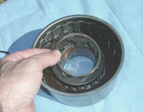
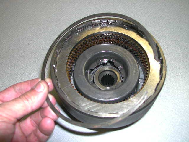
OD (or as FORD calls it - COAST) CLUTCH assembly

From the front, we will start the disassembly process on component parts. Up front after the pump is the OD clutch - Ford sometimes calls this the Coast clutch.

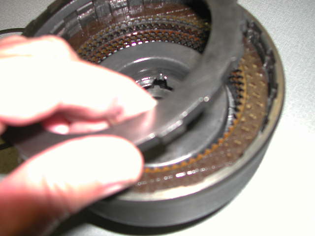
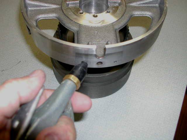
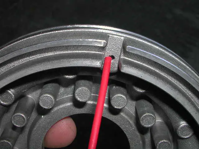
It starts with a snap ring, which is NOT under spring pressure... easy to remove.. here it is:

15286Dscn4295.jpg


Regular old screwdriver will pry it out. I measured the clearance prior to removal and it was on the outside limits. (More about all this on the rebuild section, coming up) Under the ring is a thick steel "Pressure plate". Here it is coming out...
15286Dscn4296.jpg


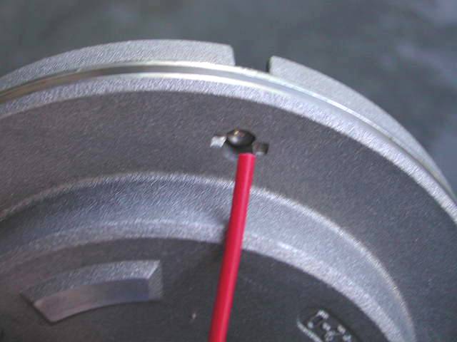
You can remove the steels and friction plates now if you like... I did, but am re-creating this for the camera, so for now I am leaving them in. There is no right or wrong order here. The next snap ring IS under spring pressure. We will devote ome time to discussing ring compressors, let's just ignore that for now and I have compressed the springs and removed the snap ring. This snap ring is a problem child. The steel retainer ring that sits on top of the springs was designed to make sure the snap ring stayed put. A new design does so even more positively. (Hey, let's revisit my insistence about that deal on snap rings being NEW! - bulletproof snap rings!) Ok the next snap ring is small, easiest removed with expanding snap ring pliers (more on that in the tools section later on) here it is coming out

15286Dscn4297.jpg


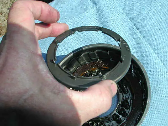
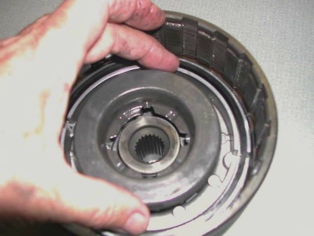
And under it the spring retainer (and snap ring retainer - old style) - those tabs sticking up are supposed to make sure the snap ring stays put.

15286Dscn4298.jpg


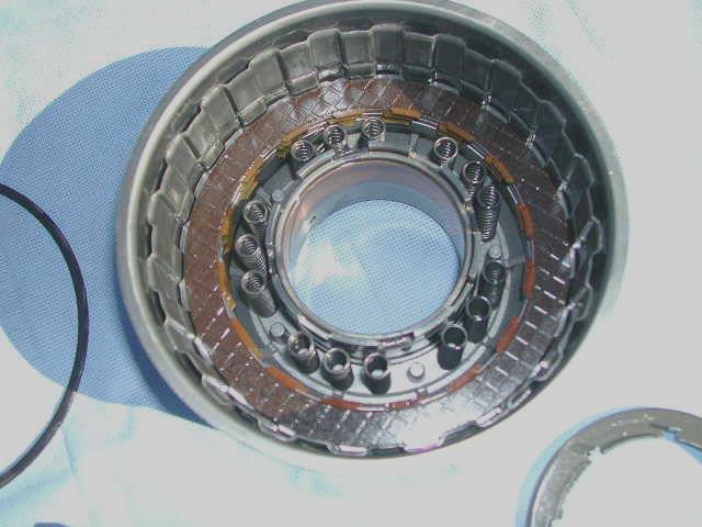
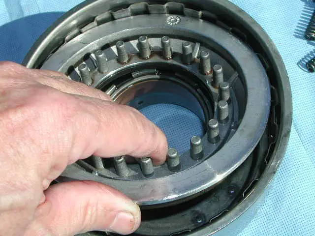
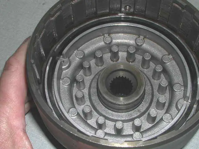
Now we see the 15 springs... in 5 groups of 3 with spaces in between

15286Dscn4299.jpg


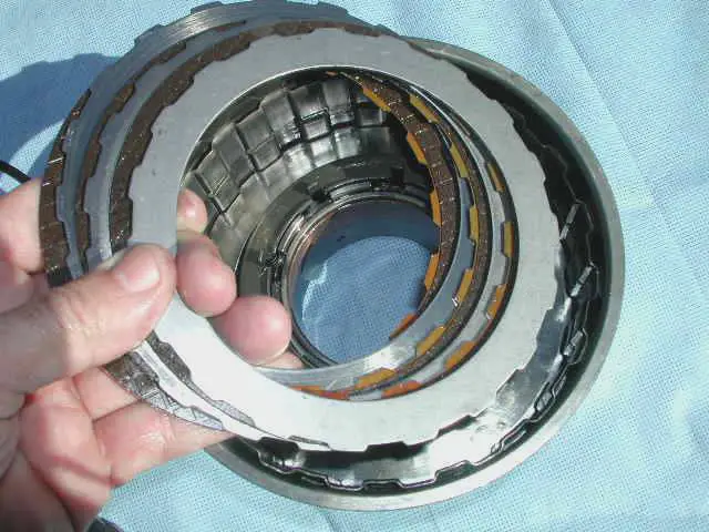
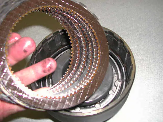
Ok, for the camera I will remove the remaining frictions and steels... [I am thinking I have the most photographed hands on Explorerforum] .. anyway, notice the mix, friction/steel/friction/steel etc.

15286Dscn4300.jpg


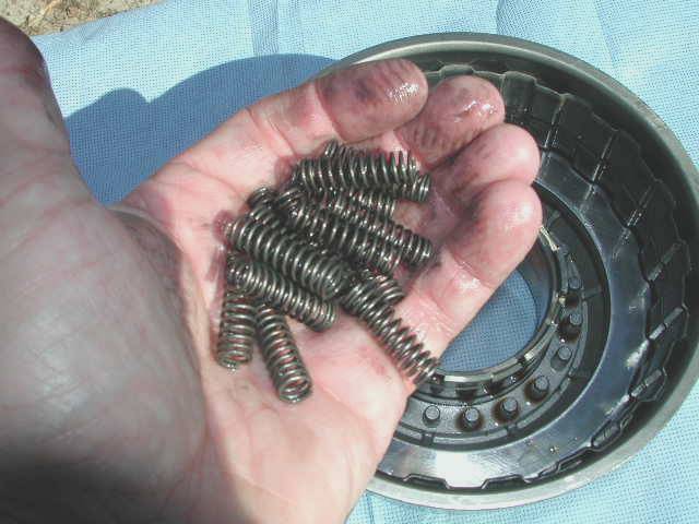
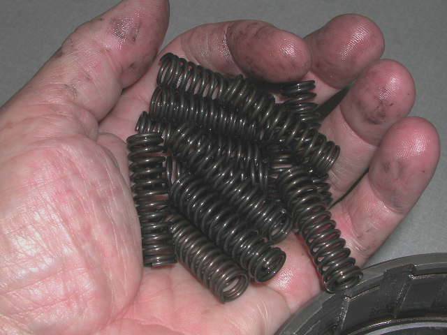
And then, a handfull of springs. In one rebuild kit we are installing, we will replace some similar springs, but not these. these will get reused.

15286Dscn4301.jpg


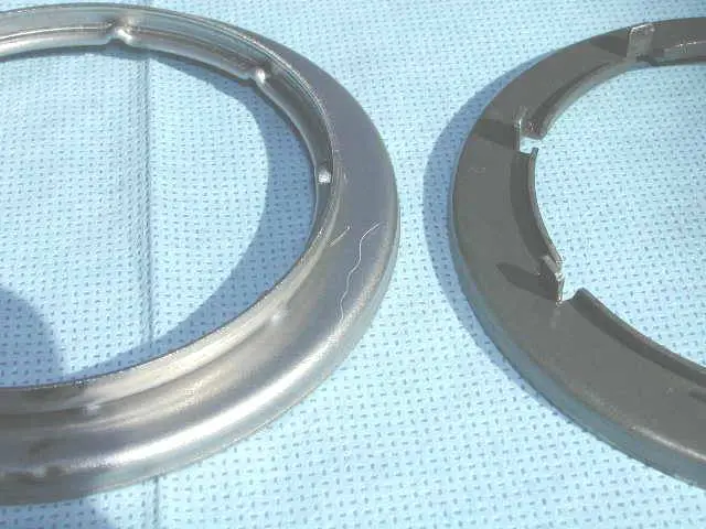
Let's take a side by side look at the new versus the old snap ring retainer... the new one the left completely surrounds the snap ring, the old used a tab bent up.

15286Dscn4302.jpg


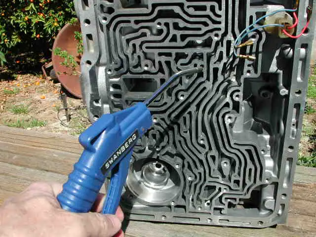
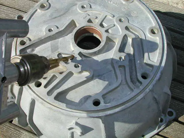
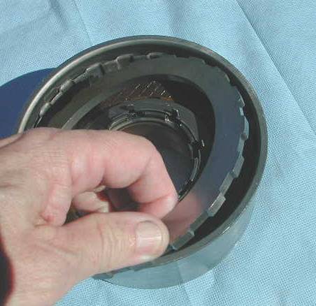
Now we are down to the piston. It should come right out. If not some air can be used - see the manual.

15286Dscn4303.jpg


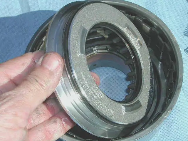
turned over you can see both the inner and outer sealing rings...

15286Dscn4305.jpg


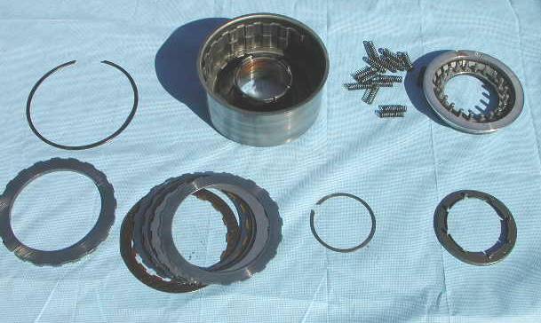
Finally, counterclockwise here is the order (ok the springs are not in the right place - sheesh) of what we took apart:

15286Dscn4306.jpg


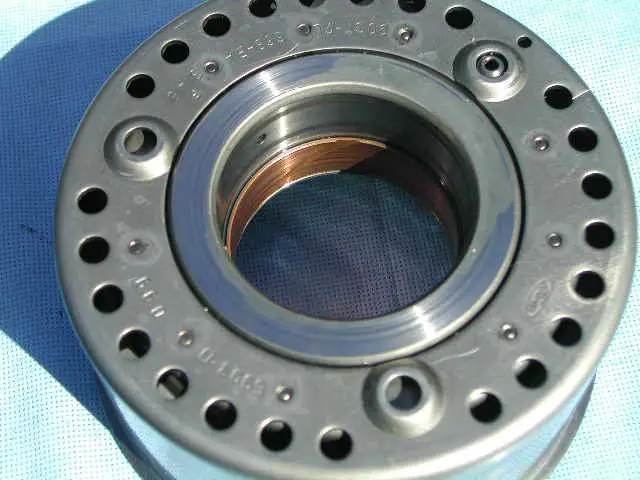
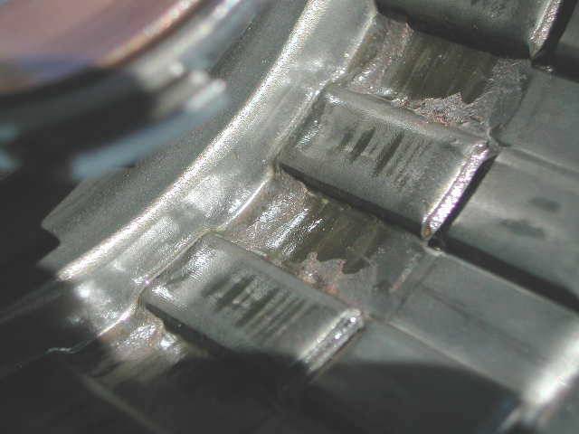
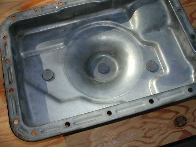
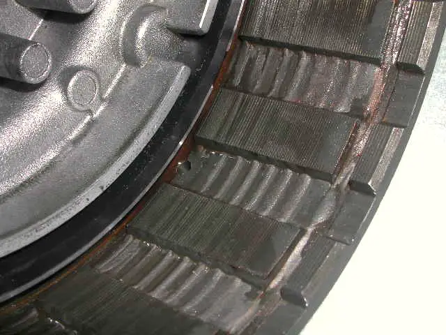
I have some issues with this stamped steel drum.... looks to me like the bearing surface is spinning eccentrically... see the wear and no-wear portions ?

15286Dscn4315.jpg


Anyway I plan to replace it. - I am not sure I'd say that replacement is a "bulletproof" item, but I am replacing mine. Also the bushing in it is a PITA to remove. I want a new bushing here anyway.

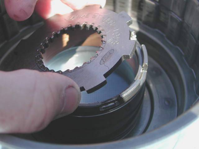
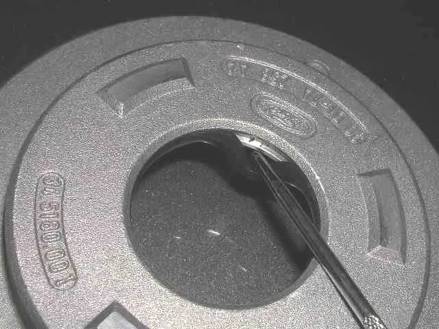
Remember the issue about the "castle washer" that Opera House complained of.. well here is the washer...

15286Dscn4310.jpg


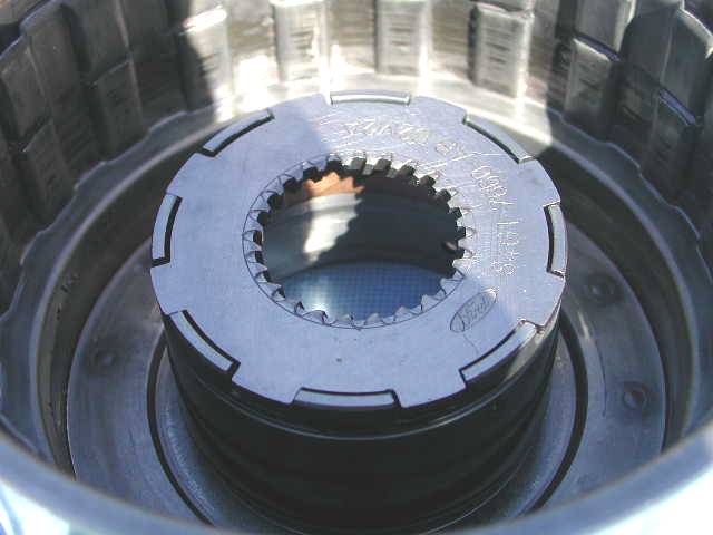
an in assembly here is where it sits, in the OD drum...

15286Dscn4311.jpg


Make sure there are no "rounded edges" in here.

Also the OD drum seems to be a dumping ground for debris. Clean it out good. This is a low mileage rebuild and look at the crud accumulated

15286Dscn4313.jpg


CASE CLEANUP


Now I'd be the first to say that paint never made anything work better, but if you remember the first forlorn pix of this trannie...

Since then... The case was sandblasted clean...machined, then washed and blown clean

15286Dscn4318.jpg


Then again cleaned with strong degreaser

15286Dscn4319.jpg


Ultimately pressure washed with hot water and blown dry....and then

Finally painted black...

15286Dscn4321.jpg


For you naked trannie guys, I can sell you posters for your garage of that last pic. (wink)

Or, if you like.... with the servo's contrasting color ! (there IS a reason, has to do with heat.) Sexy eh ?

15286Dscn4322.jpg


For you perverts here's a closer pic of that idea..

15286Dscn4323.jpg


Ok, you are asking "AND your POINT is?".... well, these servos tend to get fried by the catalytic converter. Ford has a heat shield, which I plan to upgrade DIY. But a silver cover may help resist intaking heat better.... so I decided to go Silver, one more way to save them. Made sense to me, a couple beers ago anyway.

Posters $50.


Glacier,

again your pics are outstanding, lots of useful information as usual!

p.s. I even seen a 'lil' bit of dirty fingers in those recent photos too! :p

:D


Beautiful!

That trans is looking too good to put back in a vehicle and get all dirty and greasy again.....:D

Funny you should mention catalytic converter heat on the servos, Glacier. I thought the same thing when I was under mine at the last oil change. I bent up a piece of galvanized metal to fit between the cat and trans, to deflect some of the heat. It looks a bit Mickey Mouse but it does the job. This summer I'll try to bend up a more professional looking shield.


Thanks for the compliments. as soon as your check clears your posters will be shipping ! The fluffy trannie bed time snuggle toy is on backorder. (g)


Nice Chris, real nice. Lots of good information here.

The Deep cast aluminum pan would lokk noce with that nice clean black. Shame to put it back in the vehicle. :D


Steve, Thanks. I want to put the deep pan on it, but am waiting for the redesigned one, suspect it may hold another half quart or so, and I won't have to worry about modifying the filter. Meanwhile I cleaned up the old one, sandblasted it clean, painted it and am going to put a drain plug in it... for now here it is painted:

15286Dscn4339.jpg


and the inside, with magnets (I recall someone asking about those on a post, so HERE they are!)

15286Dscn4341.jpg


I know the one at the bottom my have to go.... drain plug location. I am hoping these magnets never see any metal.


BELLHOUSING

The local place that does bellhousings (Omega Tool) does them exchange, bt I want MINE. Why? Well drain back drill out for one. Anyway, I sandblasted mine clean, and then drilled out the drain back hole, approaching it in 1/64 increments from 1/4 up to 5/16. This puppy wants to sieze the bit... I used an old electric drill (some of the forum users probably do not know what THAT is, others will recognize the port-align fixture on it)

Here is the drilling

15286Dscn4335.jpg


and here's the hole. I know that 1/16 (or a little more) of an inch does not seem all that much, but the hole seemed HUGE once I got done.
15286Dscn4336.jpg


The act of drilling ate up the seal (which I was going to replace, I say that so those thinking they may drill AND keep an old seal will know better) I punched it out from the back with a punch, easy enough. Then I used a bearing installer to remove the bushing. Piece of cake...

15286Dscn4337.jpg


Ever buy a tool and then discovered how awesome it was LATER? I picked up this set of bearing drivers on E-bay for about $35 a couple years back. MAN they are awesome and I am surprised how much I use them. The bushing I just removed? A perfect #2. I highly recommend a set to your tool box. Here's my set
15286DSCN4338_1_.JPG


And finally here is a NUDE bellhousing...awaiting a line bored bushing and a new seal...
15286DSCN4349_1_.JPG


Looks good- I took a die grinder and flared the seal side into the rounded channel (surface between the seal and bushing surfaces) if that makes sense- just a bit more than knocking down the edge of the hole. I also chamfered the exit with a cone shaped stone. Dont know if it did anything, but made me feel better....
check the holes in the pump plate and the pump- make them all the same size. My plate was fine, I opened up the pump hole- all were 5/16" when I was done.

Was your trans sitting for a while? I wondered about the rust in the pump and the plate.


Steve - good call. Yes it was. I was told it was sitting a year or two in mud. Zipee, thanks, yes I had seen them, both. Not a LOT of A4LD posts, thanks for the pointers !


Join the Elite Explorers for $20 each year.
Elite Explorer members see no advertisements, no banner ads, no double underlined links,.
Add an avatar, upload photo attachments, and more!
.


Forward Clutch

The forward clutch seems bulletproof all by itself. It has a CAST iron drum assembly. It just seems solid. Another article I read suggested that the forward clutch in most transmissions, generally speaking is NOT a problem child component. I do know that the manual valve in the A4LD could leak pressre to the forward clutch, causing burning - but we made sure that cannot happen in our rebuild by adding a "limiter" if you will, to that valve.

We are going to rebuild ours as a 6 plate, using the new spiral plates used in the 5R series.

Here's the teardown...

It all starts with a snap ring...
15286DSCN4324_1_.JPG


under that is an extra thick"steel" called a "pressure plate"
15286Dscn4325.jpg


under that is an interlaced assortment of "frictions" (clutch plates) and thinner "steels" - in our case 6:

15286Dscn4326.jpg


Next you ned a spring compressor to "squish down"
the spring retainer so you can remove the retaining ring. I'll post pics later but here is the retainer (sans ring holding it in) coming out...

15286Dscn4327.jpg


Then the springs can come out... another handful..

15286Dscn4330.jpg


(and yes that IS dirt on my hands!)

Here is the piston, still in place in the drum...

15286Dscn4332.jpg


This baby was in nice and tight. To get it out we will use air. First I noticed that the Forward drum was another good "dumping ground" for sediment. The ridges you see are sediment built up between plates.

15286Dscn4333.jpg


Ok, getting the piston out require using the old center support.... place it back on theforward drum "snout" and apply air t the left most port....FORD says 20# max, took nearly 35 for me to get to pop free...

15286Dscn4343.jpg


Maybe had I lubed it better using vaseline it might have sealed better, and 20# would have done it.. The piston has 2 seals, square cut - a small inner and a bigger outer... I took them out using a bent pick tool.... a needle would work fine... Here is the inner one coming out..

15286Dscn4411.jpg


Last thing - there is a check valve prone to getting clogged up in this piston ...blow it out using brake cleaner - from both sides..

15286Dscn4413.jpg


and then the other
15286Dscn44141.jpg


When you are done, the check ball should rattle.

The Forward drum is now APART !


Back
Top