A4LD Valve Body Rebuild Diary | Ford Explorer Forums - Serious Explorations

  • Register Today It's free!

A4LD Valve Body Rebuild Diary

Glacier991

EF Tranny Guru
Moderator Emeritus
Joined
February 8, 2003
Messages
9,824
Reaction score
84
City, State
Sacramento, CA 95827
Year, Model & Trim Level
1992 XLT
Well I'm back. When I did the A4LD rebuild diary I rather shorted the Valve body rebuild portion. Tn Explorer did a great writeup and kind of filled in the void there, but I wanted to add one of my own. In this thread I will compare valve body rebuild kits (sometimes referred to as shift kits, or correction kits), show where they overlap, recommend upgrades and try and show you how to rebuild yours. My goal (we'll see if THIS happens) is to show each bore, explain the function of that bore's contents, and maybe pass along a few tricks that you can use to get a little extra life out of your own A4LD.

[For those of you with 95 and up Explorers, I did a similar thread on rebuilding the 5R55E Valve body, here's a link to that thread] http://www.explorerforum.com/forums/showthread.php?t=140987

So.... let's start by talking about shift, or as is more accurate in this csase, correction kits. As we speak I am only aware of two main ones (If I am wrong someone please correct me) they are kits made by TRANSGO and by SUPERIOR. They are quite different and yet they do cross over.

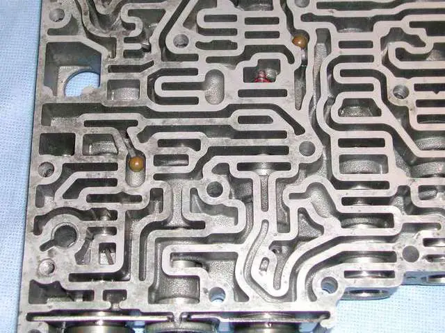
For newbies, let's briefly talk about shift kits. In the case of some transmissions shift kits can dramatically alter how your transmission operates. You can go from mild to wild. In the case of our humble A4LD, not quite to exhorbitant, yet you can make decisions about shifting. Shift kits, in a general sense, are aftermarket attempts to correct what they see as "failings" in the original design of a valve body. Let's back up, a valve body (sometimes called a control unit) is the "brains" of your transmission. A hydraulic miracle, valves, springs, passageways, etc etc. But they work, and you CAN teach an old dog new tricks!

Here are the two kits...

15286DSCN5702-med.JPG


Superior is on the left, TRANSGO in the right. Cost? I paid $22.03 for the TRANSGO and $46.99 for the Superior.

Let's see what each has in it. Starting with the more expensive Superior.
When you open the box here is what you get.... Instructions (both are VERY GOOD) and a plastic bag of "stuff"

15286DSCN57031-med.JPG


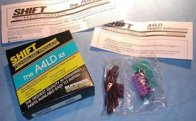
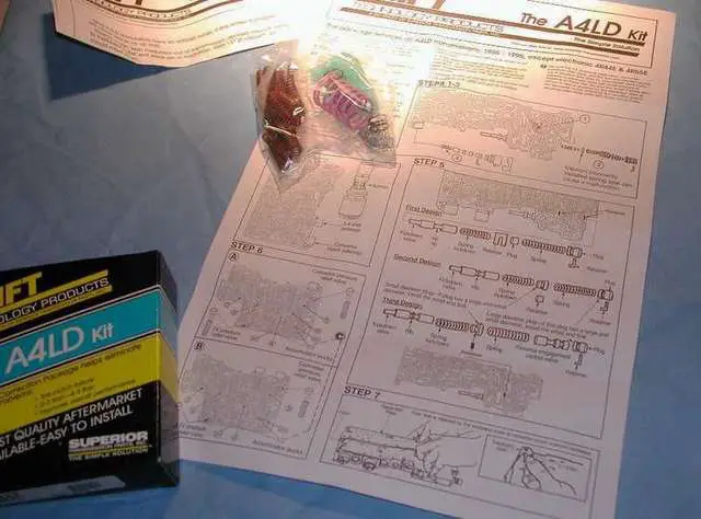
In that bag on the left are springs for a clutch... not something you will use for a simple valve body project. They require a teardown to install. On the right is the main "guts" of what you will use.... springs and a drill bit. This next pic shows you an idea of how clear and good the instructions are:

15286DSCN5704-med.JPG


As for the bag of springs etc, here they are all arranged

15286DSCN5706-med.JPG


If you ignore the drill bit, and start at the one o'clock position, in the greenish pouch you have a throttle valve replacement (located under the modulator on the side of the transmission) The next "white" one is a replacement spring for the convertor clutch shuttle valve (under the TCC solenoid - more later). The whispy spring is a "return" spring for the governor... a great IDEA...lacking in the original design of the A4LD... The blue spring and the one across from it (brown) are governor replacement springs for Aerostar and Explorer.... one or the other. The drill bit is to drill out the accumulator pucks if you so desire....and the valve body...the big pink spring is for the intermediate servo (not a valve body project), and the one next to it is for the "boost valve". The bag of springs is, as I have said, for a clutch pack.

Ok now the TRANSGO

15286DSCN5707-med.JPG


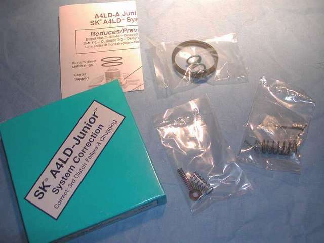
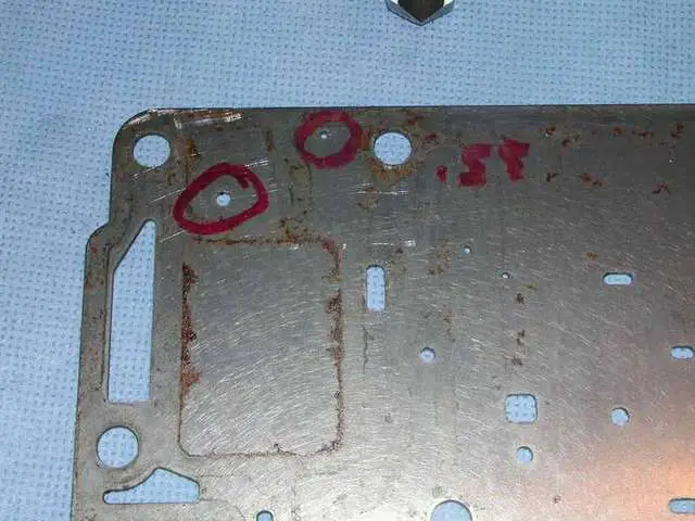
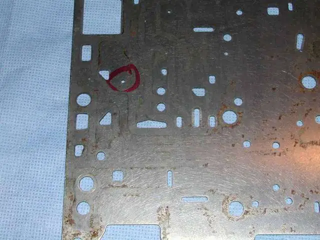
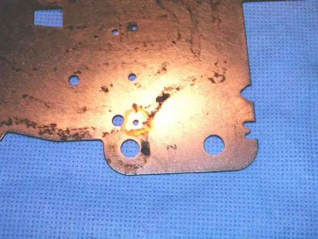
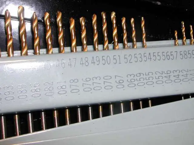
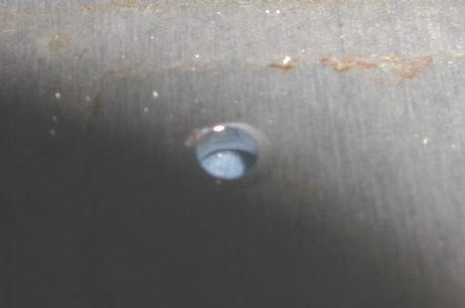
In the pouches you have at the top, new rings for the center support (tear down to install) and a replacement srping for the low reverse servo (doable as part of a VB rebuild). The other 2 are VB springs and a couple of drill bits. TRANSGO gives you instructions on drilling the separator plate (brain surgery for how your trannie will operate) and gives you the bits for that, with EXCELLENT instructions (we'll cover that in more detail later). Here are come of the "bags" of contents. Here we have the orange spring (convertor clutch valve) and the green one (torque convertor shuttle valve) as well as one whose purpose escapes me at the moment. Plus the washer for the TCC solenoid.

15286DSCN5708-med.JPG


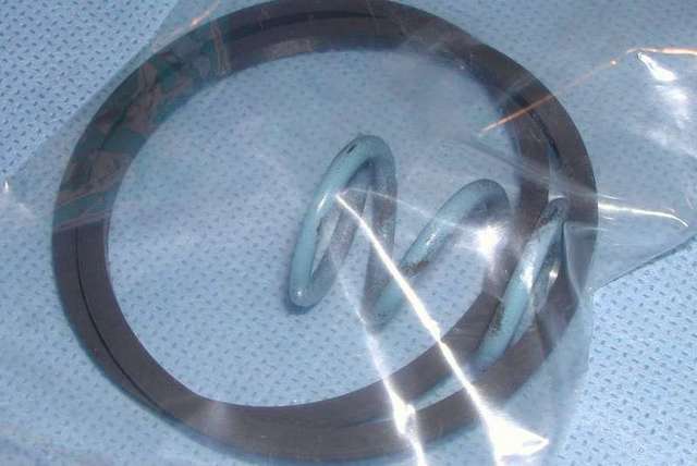
The next one is easy.. the sealing rings for the center support and the replacement spring for the low reverse servo.

15286DSCN5709-med.JPG


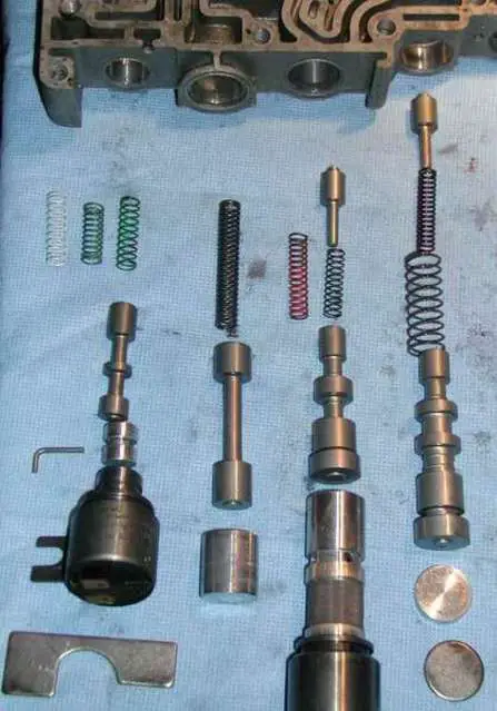
finally...the main parts...

15286DSCN5715-med.JPG


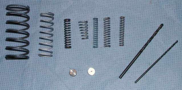
on the left are boost valve springs, inner and outer (Superior only had the bigger outer), next to them is the blue outer (color not showing, that goes with the one 2 to the right as the inner on the early model 2-3 backout valve (relax we will talk about each of these as we get to them and their functions). In between is the return spring on the cutback valve. Lastly the two white ones are inner and outer for the later style (Explorer) 2-3 backout.

The Transgo has a great exploded view of all the valve body parts, even better than the FORD factory manual

15286DSCN5711-med.JPG


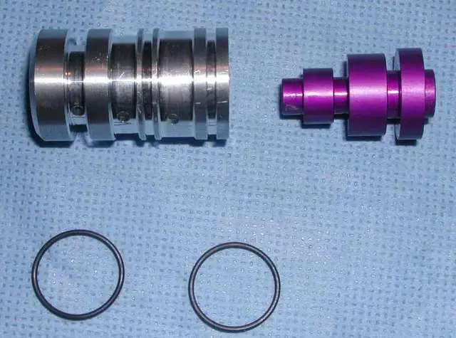
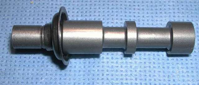
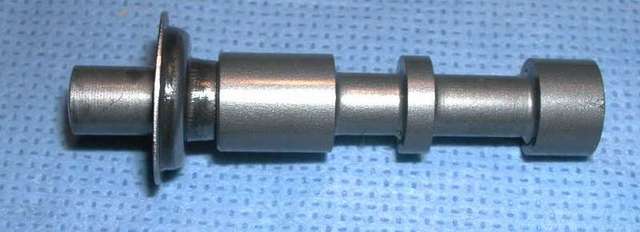
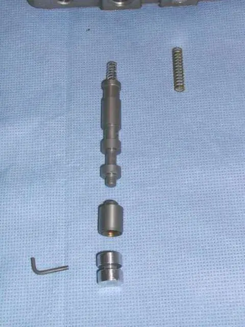
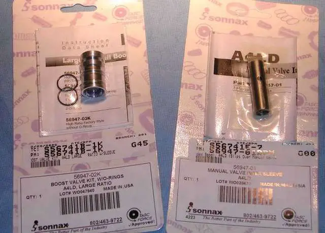
We also are going to add the Sonnax Boost valve upgrade (left) and the manual valve indexer (right)

15286DSCN5712-med.JPG


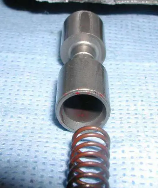
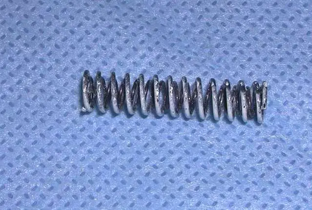
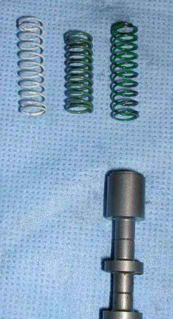
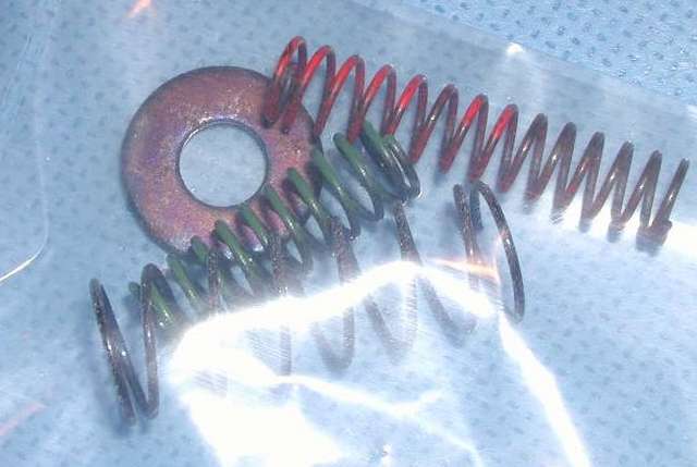
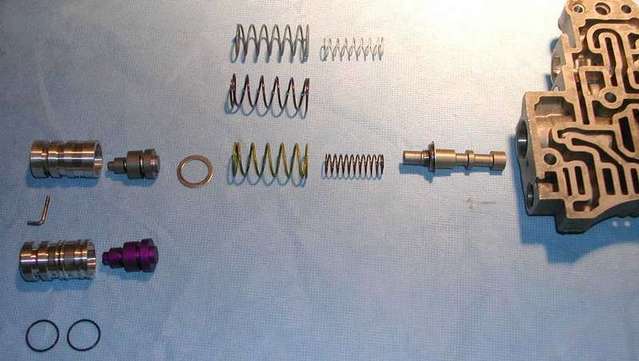
An important upgrade in my opinion is the boost valve with O-rings. Here is the old valve and springs (it looks like maybe this VB had a shift kit in it, not sure) and above it the Superior kit spring, the Transgo spring(s) and below the new valve assembly....

15286DSCN5714-med.JPG


Tomorrow we will start putting all this in place.


Join the Elite Explorers for $20 each year.
Elite Explorer members see no advertisements, no banner ads, no double underlined links,.
Add an avatar, upload photo attachments, and more!
.


BORE 208 - Oil pressure booster valve - Oil Pressure regulator

This thread will continue to be a work in progress for a while. I will post the rebuild, then come back and number each bore and "try" and explain what that part does. In some cases I know all I can do is parrot the FORD manual, because candidly, I have NO clue for some of them!

Anyway, let's continue with the upgrade to the pressure regulator and Boost valve. Important in my view. Ok... to start we are replacing the stock boost valve and sleeve with the Sonnax upgrade. Main change? O-rings

15286DSCN5716-med.JPG


Other than lubricating this well to install, not much else changes. One maor problem area though is the spring seat on the pressure regulator spool. It can go on in one of two positions.... one is correct, the other is not only wrong but can cause malfunction. Here is the RIGHT position

15286DSCN5717-med.JPG


and I fear posting this, but here is the WRONG position!!

15286DSCN5718-med.JPG


(I'll point this out here, I saw it throughout this Valve Body. Notice the pristine condition of the nitrided surfaces on the spools. Nary a mark. A good sign. Anyway... before we can put this bore together we have something to do, drill a hole - yep - right in the valve body! (the dia is .063)

15286DSCN5721-med.JPG


and finished we have

15286DSCN5722-med.JPG


That done we can put the pressure regulator spool in... notice the position of the spring seat!

15286DSCN5724-med.JPG


Installing spools can be a dicey process... it requires patience and a gentle touch. NEVER force anything too much. This one can hang up short of it's intended destination and cause you headaches. so check it is up against a "bulkhead"

15286DSCN5725-med.JPG

Then you can add the springs... the small inner one first... (easiest with the VB upright)

15286DSCN5726-med.JPG


Then the "big" one...

15286DSCN5727-med.JPG


These springs were both part of the "upgrade" in the Transgo Kit.

Now add the washer, and have it ride on the circumference of the large ring... now we can add the lubricated Boost valve....

15286DSCN5728-med.JPG


(by the way, I had not added the afrementioned washer yet, and those with sharp eyes will notice that there is no washer on top of that spring. I did before I put the boost valve in. Ok I lied. I found it minutes later and had to pull the valve out and add it. MORAL: BE VERY METICULOUS when working on a VALVE BODY!) The boost valve goes in quite a ways and is retained using one of the "L" retainers, or "keepers"...

15286DSCN5729-med.JPG


In the end, here it is...

15286DSCN5730-med.JPG


Notice how far IN the Boost valve sits...

15286DSCN5731-med.JPG


This finishes the Pressure regulator and Boost valve bore. If there is a single upgrade I think is worthwhile on the A4LD valve body spools, this may be it. Costs about $30.

I'll add more here later, on to the next bore, and a new post.


BORE 209 - Cutback Valve

NOTE: This Valve Body was so clean that I elected to remove and check the spools and springs one bore at a time. At no time did I have 2 out at once, and hence could not mix things up. IF YOU DECIDE TO PULL OUT MORE THAN ONE BORE AT A TIME, BAG EACH ONE SEPARATELY SO YOU DO NOT MIX THINGS UP!!!!


Next up... the cutback valve. This one gets a spring not existing in the "factory version of this VB.

It has a square retainer...I reached into the bore with a Q tip and pushed it up to get a grasp on it...

15286DSCN5732-med.JPG


Here is the spool out....

15286DSCN5733-med.JPG


Note the end plug. Many bores have there. So in the upgrade we add a return spring...

15286DSCN5734-med.JPG


Then lubricate ( I am using a teflon lubricant made for this purpose but anything similar will work) and reinstall. Here is the view into the end with the square keeper in place..

15286DSCN5735-med.JPG


More on this bore to be added later.


BORE 210 - Torque Demand Valve

Ok, we go around the corner. Next is the Torque demand valve. Nothing to change here. So on that note.... we come up to the question of whether you SHOULD disassemble a valve/spool if nothing is going to be done to it. As pristine as this VB was, I would not have necessarily have taken this out, but I AM doing a photo thread so I did. If I had a really cruddy VB, I'd take everything out I could. "Could"? you ask... stay tuned for the next bore. Anyway...I find a pair or forceps to be a useful VB tool (one of what I call my "rats ass" assortment of "tools" for this job.) Here is me getting hold of the "H" keeper... reminder, there is a spring behind this (as is usually the case of H shaped keepers), so before you pull this one out, if you must, guard against the spring launch... I damn near put my cats eye out across the room on this one....

15286DSCN5737-med.JPG


Here is the valve out. I inspected it (perfect).

15286DSCN5738-med.JPG


Some spools are hollow and the spring goes inside them, this is an example of that

15286DSCN5739-med.JPG


The bores where a spring is against the keeper pose a particular challenge. How do you close the "gate" without capturing the spring mid coil in the process?... I have found that if I compress the spring using something suitable (a fat "Sharpie" pen worked well for me - part of my "rats ass" asssortment,) and then slide the keeper down to corral the spring, you can then use a screwdriver in the slot to hold the spring in while you fully slide the keeper into place...WITH the spring fully on the other side..

15286DSCN5744-med.JPG


Ok that's it for this bore. More later on function and number.


BORE 211 - 1-2 Transition Valve; 2-3 Backout Valve

Ok, truth time. The next bore is a dual purpose one (this valve body has a few of those multi purpose bores with shared functions. This is the 1-2 transition and the 2-3 backout bore. It uses an L shaped keeper... which I removed with my forceps..

15286DSCN5740-med.JPG


There was an end plug which I got out.... the rest ? I could not get it come out. Often there are progressive places you can safely get to in order to coax a spool out, Not on this one. I tried for about 30 minutes.... then had to ask "How does it move within it's actual BORE range of travel? Answer ? Good. So, although there were some "upgrade" springs. this bore got reassembled "as is." Moral? "if it's not broke, don't break it."

[EDIT]

I am rebuilding another and i managed to get this one out (rather easily in fact... I pulled the valve back into the body against the srping and let is snap out ward to push out the plug.... so here is this bore's contents:

15286DSCN5909-med.JPG


the old single spring is on the right (yellow) and the Transgo offering (2 nested springs, is on the left.

Here is a closeup of the transgo springs... pre nest

15286DSCN5910-med.JPG


and once the smaller one is nested inside the bigger one...

15286DSCN5911-med.JPG


quite a bit more spring pressure here....

Here is the last one.. all ready to reinstall with the orphaned FORD spring sitting by on the right...

15286DSCN5912-med.JPG


Okay, so I finally made good on this bore for ya!


More on function later.


BORE 212 - T.V. Pressure Boost Valve

Throttle Boost Valve. Nothing to replace, but here it is


15286DSCN5741-med.jpg


another L shaped retainer, notice the groove in the plug where the L pin rests.

More later


BORE 213 - 3-2 Coast Control Valve

Next door... the 3-2 Coast valve.... again nothing to replace... but one of those H shaped retainers with a spring , so be careful.

15286DSCN5742-med.jpg


More later


BORE 214 - Kickdown Control Valve

And next up is the 3-2 kickdown timing valve (uh huh That's what it says!) another H retainer, and now whenever I say "H" real loud my cat runs and hides....

15286DSCN5743-med.jpg


more later. maybe.


BORE 215 - 3-2 High CLutch Kickdown; 3-2 Intermediate Servo Release kickdown

All right, another dual purpose bore is next.. This one is the 3-2 high clutch kickdown valve on the outer, and the 3-2 inner servo release on the inner. . Could I get them to come out? nope. So I futzed and puzzled and once again decided to make sure there worked well in their travels and call it a day. Nothing to upgrade here anyway.

More on this bore later

Going back through this I reaqlized I failed to photograph the next bore apart, BORE 216.

BORE 216 - Intermediate Servo Accumulator Valve (1-2); OD Servo Accumulator Valve; 3-4 Backout valve

pics coming

This bore has 3 functions. The deepest one is one best left alone unless you have a really grungy VB.

That farthest inner function, is the 1-2 accumulator spool. is NOT recommended to be unleashed.... there is an L shaped retainer for it. "LEAVE IT ALONE" in most cases. It is located "here"

15286DSCN5745-med.jpg


Oh a little sidebar... notice the hole with the groove in it like a screw driver slot? That is the 1-2 accumulator puck location. Notice where the groove leads. The end of the 1-2 accumulator valve!

More later


BORES 200, 201, 202 and 203

Well now we switch sides. SOLENOID TIME. The end solenoid is the torque convertor solenoid (BORE 200 - Torque Convertor Clutch Shuttle Valve)) next one over is the infamous 3-4 shift solenoid (the OD solenoid - BORE 202 - TCC clutch modulator valve) shown in exploded view..

15286DSCN5746-med.JPG


In between them is the 3-4 shift valve (BORE 201), here it is added...

15286DSCN5747-med.JPG


And finally to the right of the 3-4 solenoid bore is the 2-3 shift valve/2-3 T.V. Modulator Valve (BORE 203).... here it is added to the mix... notice now we have added some other springs... the Transgo kit and the Superior kit offer replacement springs for the TCC shuttle valve (on the end) and for the 3-4 solenoid bore, there is a transgo spring for the Convertor clutch valve (the orange one).

15286DSCN5749-med.JPG


For the TCC shuttle... there was Superior (white) transgo (middle) and stock (right, green).

15286DSCN5750-med.JPG


for the Convertor clutch valve, just the orange transgo, and it was a radical change

15286DSCN5751-med.JPG


In both cases I went with the transgo offerings.

Oh one last thing. I reused the solenoids. I cleaned them well using brake cleaner and then teflon spray. In doing so I also click tested them and clened them in both off and on positions. a 12V DC power supply comes in handy, but a car battery could work just as well...

15286DSCN5752-med.JPG


15286DSCN5753-med.JPG


holding the wires and cleaning was a bit of a trick, but I managed it...

15286DSCN5754-med.JPG


I also bent the retainers, just as I showed in the original Rebuild Diary and every thing fits tight.

More on all this later..


Bore 204

Moving along, we next come to the 1-2 shift valve. This was plain vanilla, only taken apart to show you

15286DSCN5756-med.jpg


If you notice the next door bore to the right is blocked by a stub of a valve.... the kickdown valve....so before we can remove IT, we need to skip around the corner and take apart the kickdown bore...

(more on the 1-2 function later)


BORE 207 - Kickdown Valve

[The manual valve was removed while we worked on the VB, it is bore 206, just in case you wondered why the "missing" bore.]


Ok around back to next door to where we started is the kickdown valve... It is a split valve with a retainer (square one) in the middle...

15286DSCN5757-med.jpg


When you reassemble it, you want to be sure to catch the plug for the middle with the square where it belongs. Use care!

More later


Bore 205

With the kickdown out of the way we can remove the last valve on the solenoid side.... 2nd and low boost...

15286DSCN5758-med.jpg


again, nothing really special here except inner and outer springs. Another "plug nickel" retainer.

More on this later.


Well. at this point we have removed and replaced all the spools and added upgrades. Now we shift gears. To the separator plate. We are going to resize 6 holes... mostly exhaust holes for fluid to make things happen faster. I am not going to give the exact things to do, the Transgo instructions do that well enough (BUY that kit). But here they are
15286DSCN5762-med.JPG


15286DSCN5763-med.JPG


15286DSCN5764-med.JPG


15286DSCN5765-med.JPG


and even though they give you a drill bit or so, what is REALLY handy is a set of numbered drill bits:

15286DSCN5761-med.JPG


Once you have drilled the holes here is a little trick to make the check balls seat better... take a ball bearing, situate it on/in the hole and strike it smartly with a small hammer....only do this on the "down side" that faces INTO the valve body.

15286DSCN5766-med.JPG


It gives you a small chamfer and improves seating for check balls and the like...

15286DSCN5767.JPG


(sorry for the pic quality but I think you get the idea.)

PS. I went all over both side of this plate with a straight edge razor blade to clean it up too.


There are two "relief valves" in the VB, one for the Throttle valve, and one for the Convertor. Sonnax came up with a better idea. Sonnax is on the left, stock on the right. I went with Sonnax.

15286DSCN5770-med.jpg


Oh the springs go down in the holes in the VB and the little heads go UP against the separator plate! Backwards is not good.


Check balls. (at the door)... no wait.... these are the little guys who control backward and forward flow of fluid. The Explorer had 4, and transgo says add a 5th. I took pics. I added new check balls courtesy of a friend who got em from transgo... they are brown and easy to spot in these pics... can you count 5?

15286DSCN5768-med.JPG


15286DSCN5769-med.JPG


That's it.


Ok almost done. Time for accumulator pucks. Transgo gives you two aluminum ones (stock is fiber), bored to about .040. They recommend boring them to .063 for firmer 2nd and 4th. I was reluctant to do anything and then Tn Explorer (great thread on the same topic btw) bored his and liked the results. So I went part way and bored them to .055. Here they are installed..

15286DSCN5772-med.JPG


then lastly, gasket and the separator plate. Push it down very straight - the relief valves have springs that hold it up and you need to compress them -so carefully compress straight down and install the 3 bolts that hold it in place. Oh... Don't forget the little filter!

15286DSCN5771-med.JPG


YAY ! We're done! Who's buying the beer ?

(thread is officially open for comments and ideas, suggestions, questions, criticism and *****ing... well ok, forget the last 2 <g>)

ps. Peter, your Valve Body is done.


Well this is coming later, but I said I'd try and give you some explanation...so more or less direct from the FORD manual, here is the hydraulic flow for each gear:

Park/Neutral: The manual valve (206) does not direct fluid flow to any other components. The governor has no line feed. TCC is unlocked.

Reverse: The manual valve (206) directs fluid to the 3-4 shift modulator valve (201), coast clutch apply side, reverse engagement valve (207) 2-3 shift valve (203) and the oil presssure boost valve (208). The Boost valve causes an increase in pressure. TCC is unlocked.

OD, First: The manual valve (206) directs fluid to the governor, 2-3 backout valve (211) and the low/reverse band servo release side. Governor pressure increases with ooutput shaft speed. Governor pressure starts to move the cutback valve (209) to cut off TV pressure to the oil pressure boost valve (208) and allow the oil pressure regulator valve to provide a lower (secondary) line pressure.TV or TV boost (depending on vacuum) is directed to the 203 modulator valve (203). This generates a 2-3 tv modulator pressure. As this pressure increases, and engine vacuum decreases, the 1-2 and 2-3 shifts occur at higher road speeds. TCC is off.

OD, Second: The manual Valve (206) directs fluid to the governor, 2-3 backout valve (211) and the low/reverse servo release side. Governor pressure increases with output shaft speeds. Governor pressure is now moving the 1-2 shift valve (204) to allow (secondary) line pressure to move through the D-2 shift valve (204) and the 2-3 backout valve to apply the intermediate band. During the shift, the intermediate servo accumulator valve (216) regulates back pressure on the release side of the intermediate servo. This helps cushion the 1-2 upshift. TCC is off.

OD, Third. The manual Valve (206) directs fluid to the governor, 2-3 backout valve (211) and the low/reverse servo release side. Governor pressure increases with output shaft speeds. Governor pressure is now moving the 2-3 shift valve (203). This allows the release side of the intermediate band servo to pressurize and overcome the apply side pressure releasing the intermediate band, and also allows application of the high/reverse clutch. TCC is off.

OD, Fourth, unlocked. The manual Valve (206) directs fluid to the governor, 2-3 backout valve (211) and the low/reverse servo release side. Governor pressure increases with output shaft speeds. The 3-4 solenoid is energized to move the 3-4 shift valve (201) this applies the OD band with direct line pressure. The OD servo exhausts through the OD servo release accumulator (216) to cushion the OD band apply. TCC is off.

OD, Fourth, locked. The manual Valve (206) directs fluid to the governor, 2-3 backout valve (211) and the low/reverse servo release side. Governor pressure increases with output shaft speeds. The 3-4 solenoid is energized to move the 3-4 shift valve (201) this applies the OD band with direct line pressure. The OD servo exhausts through the OD servo release accumulator (216) to cushion the OD band apply. The Convertor clutch solenois is energized (200) to reverse the fluid flow in the torque convertor and lock up the clutch.

stay tuned for more.


this is great but which is the best kit to use. i need to do that to mine because right now i have a doner valve body and i need to get a built one put it.


If all you are planning is a VB rebuild, and were only going to use ONE kit, I'd get the Transgo.


Join the Elite Explorers for $20 each year.
Elite Explorer members see no advertisements, no banner ads, no double underlined links,.
Add an avatar, upload photo attachments, and more!
.


Hello Chris, well done! When did you hit your finger, the fingernail blood stain is almost gone?

I did both my 91 and 93 Explorers in 1998, I have forgotten most of the details. Do you think that TransGo has changed anything? That all looked familier. Both of mine were relatively clean to start with. I did get everything out, and I can't remember what I drilled those pucks to. I likely compromised also, to about halfway.

Do you have any dental picks? One of the most useful valve body tools to have are picks, with 90 degree ends, to help push the parts out of the valve body. Are any of the solenoids suspect to wearing out prematurely, like the 5R55E EPC solenoid?

I will have my 91 to sell sometime soon, after I get my 93/99 done. I will have the 93 A4LD available to use or sell. I will have to decide whether to sell my 91 as is, with it's poor feeling, or work on the A4LD. The value of the whole vehicle, the transmission by itself, and the labor/cost of A4LD work, makes it hard to decide. Regards,


Back
Top