Electronic fuel pressure controller | Ford Explorer Forums - Serious Explorations

  • Register Today It's free!

Electronic fuel pressure controller

2000StreetRod

Moderator Emeritus
Joined
May 26, 2009
Messages
10,597
Reaction score
334
City, State
Greenville, SC
Year, Model & Trim Level
00 Sport FI, 03 Ltd V8
The Aeromotive Stealth 340 high flow fuel pump I installed for my M90 supercharger installation has a capacity (340 liters per hour) that greatly exceeds the demands of my SOHC V6.
340Stealth.jpg

During normal driving most of the pumped fuel is returned to the fuel tank via the intank fuel pressure regulator bypass hose.
NewFP2.jpg

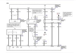
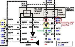
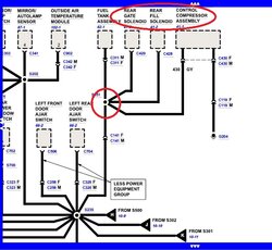
On the 3rd generation Explorers Ford implemented an electronic fuel pressure controller to reduce fuel vapor from excess fuel bypass. The system consists of a rail mounted fuel pressure/temperature sensor,
FPSensor.jpg

that provides data to the PCM and a PCM controlled fuel pump driver module (FPDM, a pulse width modulated motor speed controller)
FuelPumpDrvrMdl.jpg

that maintains optimum fuel pressure at the rails (determined by Ford to be 30 to 40 psi).

This thread documents my attempt to duplicate a less complicated implementation of an electronic fuel pressure controller on my 2000 Sport.


Join the Elite Explorers for $20 each year.
Elite Explorer members see no advertisements, no banner ads, no double underlined links,.
Add an avatar, upload photo attachments, and more!
.


Fuel pressure sensor selection & installation

Ford used several different fuel rail mounted pressure/temperature sensors in various models: 3F2E-9G756-AD, 3F2Z-9G756-AC, 5C3Z-9G756-AA. I purchased the first one listed at a bargain price from boominXplorer. I hoped it might be the same physical mounting size as my stock fuel rail pressure damper
FPDamper.jpg

but the bolt spacing and the diameter and depth of the probe was larger. So I tasked a machine shop to fabricate a custom adapter for the Banshee M90 kit rear fuel hose assembly.
FPSensor.jpg

I installed the sensor assembly on the passenger side of the rear fuel hose that equalizes fuel pressure between the passenger side and driver side fuel rails.
PresTempSnsr.jpg

I purchased a mating connector with pigtails (Ford P/N 3U2Z-14S411-UC) and 1/4" i.d. vacuum hose to connect to the sensor. Even though I don't plan to use the temperature output signal in the near future I extended all 4 wires (ground, temperature out, +5 vdc, pressure out) and enclosed them in a length of 1/4" dia. split convoluted flexible conduit.
FPTSInstalled.jpg

My plan is to route the electrical loom to the vicinity of the inertia fuel shutoff switch located at the front passenger side kick panel. The data sheet
View attachment DiffPressure100_0261230093.pdf
for the Bosch equivalent PN (0 261 230 093) explains that the sensor measures the relative pressure between the fuel port and the air port (reference). The pressure output voltage is directly proportional to the pressure difference. Ford typically connects the air port to a vacuum port (downstream of the throttle plate). I question that practice since the vacuum varies significantly with engine load but maybe the PCM takes that into account when controlling the FPDM. Because the sensor will be difficult to access after the supercharger plenum is installed I connected a 1/4" dia. hose to it and will initially connect the other end of the hose to a vacuum port. I'll perform testing with the hose connected to vacuum and plugged and compare the results.


Fuel pump controller

I planned to purchase a general purpose pulse width modulated dc motor controller and design and build my own interface to the fuel pressure sensor. However, while searching the internet for the Bosch part number data sheet I happened on just what I need: Fuel Pump Controller. I've corresponded with the developer (Madhu) and learned that the unit is capable of controlling my Aeromotive fuel pump and already has the interface to my fuel pressure sensor. The size is small enough (1.28"x1.25"x .79" high) that it should fit near the inertia fuel shutoff switch so I ordered an assembled unit.
fp_purple3.png

Using up and down pushbuttons on the circuit board I can vary the fuel pressure in 0.25 psi steps from 0 psi to at least 70 psi. My fuel pressure increased from a stock value of 62 psi to 67 psi when I replaced the stock fuel pump with the Aeromotive. The fuel pump controller has a default setting of 43.5 psi which I think I'll try initially. My newly installed high flow injectors (Siemans Deka 4) have a flow capacity of 60 lbs/hr @ 43.5 psi which should be more than adequate for my targeted 8 psi of boost. The Banshee kit fuel block has a built in mechanical fuel pressure gauge which allows me to easily check the pressure any time the engine is running with the hood open.
FuelSys2.jpg

I have received an initial start engine tune from James Henson at Henson Performance and he probably assumed I would have 65 psi of fuel pressure so the air/fuel ratio will probably be a little leaner than he planned.


avoid vacuum connection advice

I copied the following from another thread:
2000streetrod, . . .
Don't hook the vacuum line up to the sensor if you want to use it to measure real fuel pressure. The vacuum line was only used to lower fuel pressure when there is intake vacuum sucking on the injectors. On Ford vehicles this sensor was only used on electronic returnless fuel systems in where the pcm duty cycled the fuel pump to control pressure. The vacuum skews the reading off the sensor to make the pcm lower duty cycle to the pump. If there was aprox 20 inches of vacuum the fuel pressure would be about 10 psi lower in the rail than it would be reading on the sensor.
Just leave it unblocked with no vacuum line to it if you are using it to measure fuel pressure.
The FRT (temp sensor) is an NTC thermistor like most of the temperature sensors used. It shares a common pcm ground with the pressure sensor, that's why there are 4 wires instead of 5.
See attached picture, and forgive my crude Microsoft paint skills. Also the resistance values in the voltage divider circuit might be wrong. I suffer from CRS. (cant remember stuff).
FRPT%20Circuit.jpg

The above supports my concern about using a vacuum port as a reference. Below is a copy of a 2004 Explorer schematic sent to me by imp.
FPTSensSche04.jpg


I think I'll either just cap the sensor reference port like Madhu did on his motorcycle or route it to the main intake upstream of the throttle plate (filtered atmospheric reference). Connecting the sensor reference port to a vacuum port would cause the fuel pressure to vary with engine load (vacuum) and possibly complicate the custom tune.


Wiring Diagram

Just a heads up,
That wiring diagram for 2004 is wrong. It is kind of a typo, wiring diagram style. I come across a lot of this stuff, not just ford either.
Ford corrected it in 2005.
See attached picture for 2005.
 

Attachments

  • FRPT.jpg
    FRPT.jpg
    64 KB · Views: 2,916


capping the reference port

I decided to remove the hose from the pressure/temperature sensor and cap the reference port while I can still access it. That will provide a fairly stable reference and eliminate a useless section of hose.

I received notification yesterday that my assembled fuel pump controller was shipped so I removed the driver seat to gain access to under the dash wiring. I'll route the wiring from the fuel pressure/temperature sensor thru the firewall in the vicinity of the power brake booster. I'll tie into the PCM generated +5 vdc reference voltage between the C212 connector (located at the left corner of the instrument panel), C141 (located left side of engine forward of master cylinder), and C311 (left side of fuel tank in front of rear axle). I'll also route +5 vdc to the inertia fuel shutoff area for the fuel pump controller.


Fuel pump controller received

I disconnected the PCM connector to gain access to the fuel pressure/temperature sensor and removed the reference hose but didn't have time to install the cap.

The fuel pump controller arrived today. Even though I knew the dimensions I didn't fully appreciate how small it actually is until now.
FPController1.jpg

FPController2.jpg


So now I have to determine how to wire it and the sensor. The following information is provided on Madhu's website:

Pump controller wiring:
pump-controller-wiring.png


There are two sets of wires. The larger, 20 AWG wires connect to +12 Volt power and the motor. The colored Cat-5 cable connects to the pressure sensor.

Power/Motor wiring:
Wire . . . Description
Red . . . +12 Volts
Black . . Ground
Red . . . Pump motor +
Green . . Pump motor -

The black and green wires are in pairs of 20 AWG wire. There are four red wires all connected together. The connections are doubled for higher current capability needed by some of the larger automotive pumps.

Sensor wiring:
FP 1.1 harness . . . Description . . Bosch 4-pin Sensor
Blue/White . . . . . . . +5 Volts . . . . . . .2
Blue,Brown,Green . . . Ground . . . . . . . 4
Brown/White . . . fuel pressure signal . . 1
Green/White . . .fuel temperature signal .3

Apparently there is a +5 vdc regulator on the controller to power the sensor which simplifies things. I was a little concerned about using the PCM reference and signal return so that's no longer an issue. The sensor pressure output signal varies between 0.5 v for 0 psi to 4.6 v for 70 psi with 2.89 v for my target 43.5 psi. As I recall that voltage range is compatible with the analog input to my SCT PowerFlash so I'll add a breakout connector to allow datalogging fuel pressures.

I didn't notice until now that the negative side of the pump has to be returned to the controller via the green wire pair instead of to ground. Currently the negative side goes to G204 (under left side of instrument panel behind kick panel). The path is:
fuel pump - > C311 > splice 351 > C141 > splice 235 > G204
There are 18 connections to G204, 12 connections to S235, but only 5 connections to S351 located near take out C300 canister vent solenoid. I think C300 is indicated by the red arrow in the photo below and S351 is located in the wire loom indicated by the yellow arrow.
C300.jpg

I'll probably have to drop the fuel tank to delete the fuel pump return wire to S351 and splice a wire that runs to the passenger kick panel where the controller will be located.


Picture

The top picture,
Top left there is a transistor, no doubt that is turning the current on and off to the pump but what side? power or ground. Can you bench test the controller? Maybe you can get away with only having power or ground hooked to the controller.
Picture of bottom side of controller?


PWM design

I suspect the pulse width modulator is similar in design to the one I was considering for my future electric power steering pump.
125AmpPWM.jpg

It also requires both motor leads to be isolated from ground. I think that type of design requires less components or less expensive components. I've written the fuel pump controller designer asking if I can leave the fuel pump negative side grounded, ground the negative side of the controller and use the chassis for the interconnection. Below is a photo of the bottom of the fuel pump controller.
FPController3.jpg

Here's a block diagram of the controller.
frp_diagram.png

It incorporates an AVR ATtiny24 low-power CMOS 8-bit microcontroller with one 8-Bit and one 16-Bit Timer/Counter each with PWM Channels. It's remarkable to me what can be packed on a DIP with current technology. The NXP PSMN022-30PL MOSFET (30 amps continuous max drain current at 25 deg C decreasing to 12 amps at 150 deg C according to data sheet) drives the pump motor. My fuel pump draws about 10 amps at 67 psi so as long as the MOSFET temperature stays below 150 deg C it should be fine. I'll use my remote reading thermometer to measure the MOSFET temperature and add a heat sink if it doesn't stabilize below 100 deg C. If everything works as planned I'll enclose the controller in a small case for physical protection. I can drill holes in the case for the up and down button control but shouldn't need them since I plan to run at the default pressure.


Routing the sensor loom

I resumed work today after spending a month on other activities. The only thing I accomplished was to route the sensor loom from the engine compartment thru the firewall. I attached the sensor loom to the windshield wiper loom with cable ties.
FPTSLoom1.jpg

It comes thru the firewall via a hole I punched in the transmission range selector cable grommet.
FPTSLoom2.jpg

In addition to the vaccum/boost gauge hose, the air/fuel ratio meter O2 sensor loom and the ATF temperature/engine oil pressure & temperature loom.


Mystery connector

My Haynes Repair Manual states "on models through 2000, the fuel pump/sending unit electrical connector is attached to the left frame rail" in front of the fuel tank. This connector is not shown on any of my 2000 Explorer/Mountaineer Ford Wiring Diagrams. If it is present on my Sport, and contains the fuel pump ground wire, then I will be able to determine with a resistance measurement if there is a ground splice between the connector and the fuel pump. If there isn't, then I won't have to drain the almost full tank and drop it to interrupt the ground path for the controller connection.

The power (positive) source for the fuel pump should be interrupted after the inertia switch. According to my wiring diagrams:

inertia switch C203 PK/BK wire > C212 > C141 > C311 > fuel pump

None of the above connectors are the Haynes mystery connector.
C212 is located left corner of instrument panel, near cowl panel grommet
C141 is located left side of engine, forward of master cylinder
C311 is located left side of fuel tank, in front of rear axle

I may be able to locate the electronic fuel controller behind the dash on the driver side instead of the passenger side. If so, the wire lengths will be shorter and I won't have to remove the passenger seat for access.


Connector

The fuel pump / sending unit connector is the one that you would have unplugged when you put your fuel pump in. It is the pigtail coming off the fuel pump unit. It is connector C311. "attached to the left frame rail in front of the fuel tank" (It comes off the TOP off the fuel tank, not really front of tank)
Its a shame you cant use C141 because of the gate solenoid and air suspension.
 

Attachments

  • 2000 ex fuel pump ground.jpg
    2000 ex fuel pump ground.jpg
    60.4 KB · Views: 2,258
  • ground 2.jpg
    ground 2.jpg
    112.4 KB · Views: 2,013


Connector

Good news is you should not have to drop the tank if you go to C311 to separate the circuit because the splice S351 is between C311 and C141, not between C311 and tank.


Mystery connector exists

I found the mystery connector in the location identified by Haynes. I now think this connector is C141 even though my wiring diagram connector table states it is located at the left side of engine, forward of master cylinder. It has four rows of four pins and matches the pinout in the wiring diagrams for C141.
FPC1.jpg

I disconneted the male and female parts and measured the black wire resistance from the fuel pump side to chassis ground and found it to be open (good news). It was a short to chassis ground on the other connector. The wiring comes up thru a floor grommet just below the driver seat and then is routed to the driver side channel.
FPC2.jpg


FPC3.jpg


The wiring bundle rises vertically behind the driver side kick panel and comes out behind the instrument cluster near connector C212 in a difficult to access location.
FPC4.jpg

I decided to interrupt the two wires at the bottom of the kick panel and snake the extensions upward following the same path as the wiring bundle.

I'll probably mount the fuel pump controller on a bracket extending between the OBD II port connector and where it mounts. "A" below identifies the trailer type connector to the ignition on wire I used to power the air/fuel ratio meter. All power for the fuel pump controller and pump comes from the inertia switch pink/black wire.
FPC5.jpg

"B" above identifies the two pin connector for datalogging the air/fuel ratio. I'll replace it with a four pin connector so I can datalog fuel pressure as well as A/F ratio.

I found the pink/black wire (on the right).
FPC6.jpg

Unfortunately, there are three black wires (on the left) so I have to determine which one comes from the fuel pump. According to my wiring diagrams there is a splice (S302) located near the liftgate washer/pump motor for the rear lights, cargo lamp, trailer ground wire, trailer tow park lamp relay and door lock relay that goes to S235 located inside of left rear door jamb. Since I only have two doors the splice may be elsewhere. Then S235 goes to G204 under left side of I/P, behind kick panel. Anyway, I checked my door lock/unlock and my cargo light and they work with the assumed C141 disconnected. Since I don't have an air suspension control system I don't care about S351 that connects to the rear gate solenoid, rear fill solenoid, and air suspension control compressor. I just need to make sure there are no other splices between the assumed C141 and the wires I intend to interrupt at the base of the driver kick panel.


Wires

No rear air suspension so that wont matter, but do you really want to disable the rear hatch lock actuator? That doesn't sound like you, you usually want to keep everything working. IE cruise control etc.
You might be able to separate the rear gate lock actuator from the circuit and give it a separate ground if you decide you don't want to use the key to unlock the back gate?


rear gate solenoid

The rear gate solenoid operates valves that block air from entering or leaving the air suspension control shock absorbers. The liftgate lock switch and the liftgate lock motor use S302 which is still functional with the assumed C141 disconnected.


wires

Oh, I was thinking the rear gate solenoid was the lock actuator. Now it makes sense. And very convenient to not have air suspension when modifying the fuel pump circuits. lol.


Data inconsistencies

I hate data inconsistencies because of potential damage, time waste, and rework. The Bosch data sheet I used to plan the fuel pressure sensor connection shows a pin out drawing and signals:

Pin1 = Ground, Pin2 = NTC, Pin3 = +5 vdc, Pin 4 = Press out
The pin out agrees with the Standard Motors replacement part:
FPSPins.jpg


The fuel pressure controller connection instructions agree with the pin out numbering but not signal names:

Pin connections are 1234 left to right looking at sensor pins, fuel port down
1 - fuel pressure signal
2 - +5v
3 - fuel temperature signal
4 - ground

The signal names are in reverse order and agrees with the Ford wiring diagrams furnished by imp and 4pointslow. I have not been able to find a data sheet for the Ford part number. So now I have spend time experimenting with the sensor to determine which order is correct.


Splice 235?

I couldn't electrically determine which of the three black wires was the one I should cut so I unbundled the wires to physically trace the one from C141. I'm glad that I did because I think I found the equivalent of S235 in the channel even though it had only seven wires.
FPC7.jpg

I cut the C141 wire where it entered the splice and then spliced 12 gauge wire to it and covered the connection with shrink wrap. 12 gauge is larger than the wire I cut but 14 gauge would have been smaller than the wire. I temporarily grounded the other end of the extension and then turned on the ignition to make sure the fuel pump came on. I even started the engine for a few seconds. My long and short fuel trims for both banks are at about 0.5. I'm surprised I don't have any DTCs. Probably because the vehicle hasn't been driven yet.


Join the Elite Explorers for $20 each year.
Elite Explorer members see no advertisements, no banner ads, no double underlined links,.
Add an avatar, upload photo attachments, and more!
.


FPC container

I had planned to mount the fuel pressure controller (FPC) in a box but I was unable to find anything with suitable dimensions. So I cut the base off of an empty cologne plastic bottle.
FPC8.jpg

I'll apply double sided sticky foam tape to the bottom of the FPC to attach it to the bottle. The open top will allow observing the power on LED and depression of the up and down fuel pressure adjust buttons if required. I'll install two four pin connectors: one for fuel pump power and one for the fuel pressure sensor.


Back
Top