HID Projector Retrofit - Phase I | Ford Explorer Forums - Serious Explorations

  • Register Today It's free!

HID Projector Retrofit - Phase I

I've been working on this for well over 4 months now, and it is finally in good enough shape that I thought I'd share... I'll call that Phase I: Installation of custom mounting plate, with Up/Down, Left/Right and Rotational Adjustments.

Phase II will be making a custom shroud.
Phase III will be the final installation.

2007 Explorer with FX-R Bi-Xenon.

First off, I have to mention that I wanted to be able to get full adjustment over this projector and I really didn't like the idea of just mounting the projector to the original reflector. No offense to anyone who has gone that route, but that just was not the way I wanted to go... So I ended with this setup:

Assembly-Installed-FrontLeft.jpg


Assembly-withlens-FrontLeft.jpg


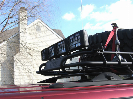
The Up/Down adjustment is done using the original screw. The Left/Right adjustment is done by turning a shaft that protrudes through the back of the assembly, shown below in middle left of the pic (without the eventually knob):

Assembly-Installed-Rear.jpg


The assembly consists of:

The Projector Mounting Plate, with slots to provide rotational adjustment. 1/4" Aluminum.
Parts-RotationRingwithRodEnds-Front.jpg


The Main Mounting Plate. 1/8" Aluminum.
MainPlate-LeftSide1.jpg


The 2 plates get assembled with Booted Rod Ends to provide pivot points.
Parts-RotationRingwithRodEnds-Side.jpg


Assembly-WithoutProjector-Right.jpg


I had to slice off the lip from the projector in order to make the rotational ability to work in limited space.
Step1-Cuttingoutthelipontherefle-1.jpg


Assembled, using a mockup rod for the Left/Right adjustment. The final assembly gets the miniature U-Joint seen earlier.

Assembly-RideSide1.jpg


Still a lot of work left to get all that on the Ex, but getting there... I'll do a write-up, with parts list, diagrams, cost and more pics, if anyone is interested.


Join the Elite Explorers for $20 each year.
Elite Explorer members see no advertisements, no banner ads, no double underlined links,.
Add an avatar, upload photo attachments, and more!
.


that is gonna look really good once you have a good shroud on it. Great work


Finally got around to start fabricating a shroud. This is the 1st attempt, and the fit is not all that great, but it is starting to come together:

For the prototype, I'm using some High Impact Styrene Thermoform Plastic (1/16" thick), but the final product will use Black ABS Thermoform Plastic Sheet (also 1/16" thick).

Shroud.jpg


Shroud_Installed-No_Lens.jpg


Shroud_Installed-with_Lens.jpg


As seen on the last picture, I don't have that bottom curved ridge positioned quite right, I need to move left about 1/2" so that it can "slide" under the cover's edge.

The protrusion on the top right is there to hide the Up/Down adjustment tab and screw.


Looking good, how did you make the shroud though?


Vacuum forming, using an apollo shroud, a cut out piece of a reflector and a metal box. Set them up on the vacuum table, eye-balling the position of the pieces. The process is a lot more straightforward than I though. Getting the right result, well, that's another story. I've got to make a more accurate mold now, since I have a better idea of how to fit it all together.


wow thats impressive. Looking Good, Wish I was coordinated to do something like that.. I'm defiantly going to look into vacuum forming some more. Just heard about it now for the first time and it seems like a good thing to know because I plan do projector retrofits soon.

Be sure to keep us updated with more pictures! :)


Well, you asked for it...

Shroud Prototype II did not turn out anywhere near as well as I was hoping... Complete lack of features, although the fit is almost perfect.

This time, I used an entire reflector, trimmed a piece of 1/4" MDF to fit recessed in the bowl and laid the Apollo shroud and a block of wood on top of all that:

MockupinReflector-Side.jpg

MockupinReflector-Top.jpg


Unfortunately, I think this arrangement creates such a large chamber that the vacuum table is not able to suck down enough air to reproduce the details inside the bowl.

This is what the piece looks like, off the table, before trimming:

Shroudbeforetriming.jpg


Once trimmed, it looks blah...

Shroud-Side.jpg


Inside the housing, even more blah...

Installedinheadlight-Side.jpg


I think the next thing to do it to trim the bottom of the reflector, so that it sits lower on the vacuum table and/or leave the material in the oven a minute longer to make it softer... Hopefully I can work on that idea this weekend!


Parts list

I know it's been a while since this post but I would actually like to get a parts list and etc for this conversion I'm looking to do this to my explorer.
Thanks!


You sure you want to do that? I don't remember exactly what the overall cost was, but it started adding up with the custom machined parts and all that jazz! I think the plates themselves were upwards of $200...


Well I guess I am more interested in the projectors that you used for yours! I have a shop where I have already baked my headlights (which didn't do anything! I figured out it was silicone glue which doesn't heat up!) but got them off and wanted to retrofit them in! I couldn't find much or know a good h13 projector and stumbled into this and saw what you did and liked it! Plus I have some weird haze on my lens cover and wanted to see if I could find a smooth surface one too or at least on to replace to get rid of that ugly hazing! Or I would just like I guess to optimize the hid system that I have hard wired into my car at this point to it's full potential! I have always had the ddm tuning h13 6000k hids and 3000k for the fogs. Both very bright set of hids but in the reflector housings makes them bright to a certain point as you know and then they are not putting out what they could be and I just want to optimize that lighting.

Thanks for the information!


Back
Top