aldive
Elite In Memoriam
- Joined
- January 17, 2001
- Messages
- 24,667
- Reaction score
- 28
- Year, Model & Trim Level
- 1999 XLT
In my never-ending pursuit for a more efficient truck with enhanced gas mileage, the next logical step for me was the replacement of the engine driven fan with an electric cooling fan. In addition to a boost in fuel economy, this procedure will also net some horsepower ( the fan manufacturer claims up to 17 free crank horsepower from a fan change ).
A little research showed the recommended flow rate for my V6 engine is 2000 CFM, consequently I decided to use a Flex-a-Lite Black Magic Fan 150 ( Dead Link Removed ). This 15 inch fan assembly with nylon shroud moves 2800 cu ft of air (Airflow-Cu. Ft./Min. at 0º Static Pressure ) and draws 13.9 amps. For control of the fan, it has a Built in control box with adjustable thermostat, A/C relay and manual switch connection. I did not want an electric fan that attached to the radiator with tie wraps.
The fan was ordered from Summit Racing ( http://store.summitracing.com/default.asp?target=/product.asp?p=589&searchtype=ecat ) for $217.85, UPS 2nd day to my door.
Upon opening the box to check that all parts were present, I found a rugged fan with built in shroud as well as all the other needed goodies including wire ( though not enough ) and crimp on connectors. The instructions were next to worthless. All of the structural parts are heavy duty and appear very durable.
The first step in the installation was the removal of the existing factory fan and clutch using a Ford Fan Clutch Wrench Kit facilitated this. The specialty tools make this job easy. I got mine on the tool lone program from the local AutoZone store ( if you have never used this program, it is great; you put a deposit down on a credit card and take the tool for as long as you want, bring it back for credit or just keep it - the deposit, which is the retail price of the tool, for the fan clutch removal tools it was $32.10 ). After unbolting the fan clutch, the factory shroud was unbolted ( 2 bolts ) and the fan assembly and shroud was lifted out as a unit, with a little effort and some cursing. These parts were saved in the dubious event that they might be required at a later date.
After comparing the size of the factory fan a/shroud with the new one, I had some worries about whether this was a good idea after all.
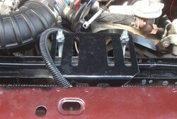
Four threaded rods were screwed into the shroud assembly. The new fan assembly was held in place from the top while my son slipped on the bracket for the bottom and then tightened it down. The support brackets are a rather shiny silver color; I painted them black to match the other under hood items. It’s a shame that they don’t make auto model specific brackets that allow the unit to be bolted on with the factory shroud hardware for a much cleaner looking install.
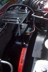
The electrical install is straightforward. First the battery is disconnected. Next, the 12 v positive terminal is connected to a switched 12 v source at the fuse block with an Add A Circuit adaptor (Dead Link Removed ). The B terminal is connected directly to the positive side of the battery with an inline circuit breaker ( included in the kit ) that is attached with Marine-Tex behind the battery to the inner fender wall. The G terminal is the ground. The C terminal is spliced into the AC clutch positive lead. The M terminal is for a Manuel Control Switch; this switch will allow you to override the thermostatic switch when extra cooling is needed or as a backup in the unlikely event of a thermostatic switch malfunction. It is connected to a toggle switch ( mounted to the top part of the console next to the SkiFi XM radio. ). The switch is powered by an ignition switched 12 v supply ( at the fuse block with another Add A Circuit adapter ). The temperature sensor probe from the control unit must be in good contact with the radiator; therefore, it was simply slipped in among the cooling fins. All wiring is neatly secured and enclosed in wire looms.
To set the thermostat, I hooked up my OBD II scanner (http://www.autoxray.com/products.aspx?sub=scanners&id=2 ) and set it to display coolant temperature. Subsequently the thermostat control is turned clockwise completely. The truck is cranked and is run until the scanner shows the temperature to 195 F; the control was turned counterclockwise until the fan turns on. The temperature display returns to 192 F very quick, and remained there.. With the factory fan, the normal operating temperature was 190 F.
The install took about 2 ½ hours working at a comfortable pace.
During operation, the fan is extremely quiet and there is a slight but noticeable feel of increased power. The OBD II scanner was left attached and the coolant temperature was monitored during the road test; the temperature was unwavering at 192 F. During preliminary evaluation in the Florida heat, there have been no overheating issues.
I shall report on any overheating problems after driving the truck around town in traffic. A lengthy road test will be made very soon to determine the installation’s effect on gas mileage.
So far, I am very pleased with this modification.
A little research showed the recommended flow rate for my V6 engine is 2000 CFM, consequently I decided to use a Flex-a-Lite Black Magic Fan 150 ( Dead Link Removed ). This 15 inch fan assembly with nylon shroud moves 2800 cu ft of air (Airflow-Cu. Ft./Min. at 0º Static Pressure ) and draws 13.9 amps. For control of the fan, it has a Built in control box with adjustable thermostat, A/C relay and manual switch connection. I did not want an electric fan that attached to the radiator with tie wraps.
The fan was ordered from Summit Racing ( http://store.summitracing.com/default.asp?target=/product.asp?p=589&searchtype=ecat ) for $217.85, UPS 2nd day to my door.
Upon opening the box to check that all parts were present, I found a rugged fan with built in shroud as well as all the other needed goodies including wire ( though not enough ) and crimp on connectors. The instructions were next to worthless. All of the structural parts are heavy duty and appear very durable.
The first step in the installation was the removal of the existing factory fan and clutch using a Ford Fan Clutch Wrench Kit facilitated this. The specialty tools make this job easy. I got mine on the tool lone program from the local AutoZone store ( if you have never used this program, it is great; you put a deposit down on a credit card and take the tool for as long as you want, bring it back for credit or just keep it - the deposit, which is the retail price of the tool, for the fan clutch removal tools it was $32.10 ). After unbolting the fan clutch, the factory shroud was unbolted ( 2 bolts ) and the fan assembly and shroud was lifted out as a unit, with a little effort and some cursing. These parts were saved in the dubious event that they might be required at a later date.
After comparing the size of the factory fan a/shroud with the new one, I had some worries about whether this was a good idea after all.
Four threaded rods were screwed into the shroud assembly. The new fan assembly was held in place from the top while my son slipped on the bracket for the bottom and then tightened it down. The support brackets are a rather shiny silver color; I painted them black to match the other under hood items. It’s a shame that they don’t make auto model specific brackets that allow the unit to be bolted on with the factory shroud hardware for a much cleaner looking install.
The electrical install is straightforward. First the battery is disconnected. Next, the 12 v positive terminal is connected to a switched 12 v source at the fuse block with an Add A Circuit adaptor (Dead Link Removed ). The B terminal is connected directly to the positive side of the battery with an inline circuit breaker ( included in the kit ) that is attached with Marine-Tex behind the battery to the inner fender wall. The G terminal is the ground. The C terminal is spliced into the AC clutch positive lead. The M terminal is for a Manuel Control Switch; this switch will allow you to override the thermostatic switch when extra cooling is needed or as a backup in the unlikely event of a thermostatic switch malfunction. It is connected to a toggle switch ( mounted to the top part of the console next to the SkiFi XM radio. ). The switch is powered by an ignition switched 12 v supply ( at the fuse block with another Add A Circuit adapter ). The temperature sensor probe from the control unit must be in good contact with the radiator; therefore, it was simply slipped in among the cooling fins. All wiring is neatly secured and enclosed in wire looms.
To set the thermostat, I hooked up my OBD II scanner (http://www.autoxray.com/products.aspx?sub=scanners&id=2 ) and set it to display coolant temperature. Subsequently the thermostat control is turned clockwise completely. The truck is cranked and is run until the scanner shows the temperature to 195 F; the control was turned counterclockwise until the fan turns on. The temperature display returns to 192 F very quick, and remained there.. With the factory fan, the normal operating temperature was 190 F.
The install took about 2 ½ hours working at a comfortable pace.
During operation, the fan is extremely quiet and there is a slight but noticeable feel of increased power. The OBD II scanner was left attached and the coolant temperature was monitored during the road test; the temperature was unwavering at 192 F. During preliminary evaluation in the Florida heat, there have been no overheating issues.
I shall report on any overheating problems after driving the truck around town in traffic. A lengthy road test will be made very soon to determine the installation’s effect on gas mileage.
So far, I am very pleased with this modification.