O2 sensor wiring issue | Ford Explorer Forums - Serious Explorations

  • Register Today It's free!

O2 sensor wiring issue

iCasper

Member
Joined
February 4, 2015
Messages
14
Reaction score
0
City, State
Canary Islands
Year, Model & Trim Level
97 SOHC Explorer II, 2WD
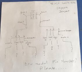
I needed to change all 02 sensor wires due to some cable burns. I got 4 sensors.
Each sensor with4 pins, 2 for the heater and 2 for the signal.

In the PCM Pinout 4.0L SOHC as the following pins:

The heater is mass controlled by the PCM and connected with a fuse to (+) on the battery.
93 Heated Oxygen Sensor #1 Heater
94 Heated Oxygen Sensor #2 Heater
95 Heated Oxygen Sensor #3 Heater
96 Heated Oxygen Sensor #4 Heater

Signals:
35 Heated Oxygen Sensor #3 Input
60 Heated Oxygen Sensor #1 Input
61 Heated Oxygen Sensor #4 Input
87 Heated Oxygen Sensor #2 Input

91 Signal Return ???

I guess Pin 91 is the return wire for the input wires? How are the o2 sensor harnesses wired?
From Pin 91 to each harness or from Pin 91 to Sensor1, then to Sensor2 and so on?

The PCM throws only codes p1131 p1151.


Join the Elite Explorers for $20 each year.
Elite Explorer members see no advertisements, no banner ads, no double underlined links,.
Add an avatar, upload photo attachments, and more!
.


I needed to change all 02 sensor wires due to some cable burns. I got 4 sensors.
Each sensor with4 pins, 2 for the heater and 2 for the signal.

In the PCM Pinout 4.0L SOHC as the following pins:

The heater is mass controlled by the PCM and connected with a fuse to (+) on the battery.
93 Heated Oxygen Sensor #1 Heater
94 Heated Oxygen Sensor #2 Heater
95 Heated Oxygen Sensor #3 Heater
96 Heated Oxygen Sensor #4 Heater

Signals:
35 Heated Oxygen Sensor #3 Input
60 Heated Oxygen Sensor #1 Input
61 Heated Oxygen Sensor #4 Input
87 Heated Oxygen Sensor #2 Input

91 Signal Return ???


I guess Pin 91 is the return wire for the input wires? How are the o2 sensor harnesses wired?
From Pin 91 to each harness or from Pin 91 to Sensor1, then to Sensor2 and so on?

The PCM throws only codes p1131 p1151.
hi my car 4 wd mine 3 piece sensor is this connections compatible ?
thanks


I needed to change all 02 sensor wires due to some cable burns. I got 4 sensors.
Each sensor with4 pins, 2 for the heater and 2 for the signal.

In the PCM Pinout 4.0L SOHC as the following pins:

The heater is mass controlled(+) on the battery.
93 Heated Oxygen Sensor #1 Heater
94 Heated Oxygen Sensor #2 Heater
95 Heated Oxygen Sensor #3 Heater
96 Heated Oxygen Sensor #4 Heater

Signals:
35 Heated Oxygen Sensor #3 Input
60 Heated Oxygen Sensor #1 Input
61 Heated Oxygen Sensor #4 Input
87 Heated Oxygen Sensor #2 Input

91 Signal Return ???


I guess Pin 91 is the return wire for the input wires? How are the o2 sensor harnesses wired?
From Pin 91 to each harness or from Pin 91 to Sensor1, then to Sensor2 and so on?

The PCM throws only codes p1131 p1151.
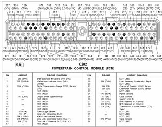
I need a diagram showing the color codes of the pin outputs of my ecu module, which I shared the hi picture of, and where they are connected, I have up to 34 in the picture, my vehicle is 97 explorer xlt soch engine, thank you all

pcm.jpeg


pcm1.jpg
pcm2.jpg
pcm4.jpg
pcm2.jpg
pcm3.jpg


I don't have time rite now to look at pin outs and diagrams
Someone will help
Perhaps @J_C could help he knows his ****
And has all the wiring diagrams


02 1.PNG

02   2.PNG

02    3.PNG

02    4.PNG

best i can do
hope this helps


I don't have time rite now to look at pin outs and diagrams
Someone will help
Perhaps @J_C could help he knows his ****
And has all the wiring diagrams
ok i want help from j_c
thanks


1) Determine if you have 3, or 4 O2 sensors.

2) Download this: MEGA

3) Unzip that, look at engine-controls-4-of-4-2.pdf if you have 4 O2 sensors, or look at engine-controls-4-of-4.pdf if you have 3 O2 sensors. This shows the wire colors. It also shows some of the wires to the ECM and the pin # of the connector. Pins are just numbered like shown in Donalds' picture, pin 1 at top left, pin number increasing across the row horizontally and sequentially again on the next row from the left again. You should also notice the wire colors matching.

4) To see the other O2 wires going to PCM, they go left on the PDF diagram onto a prior diagram like engine-controls-3-of-4.pdf This 3-of-4 file may have name reversed, meaning you many need 3-of-4 for a 4-of-4-2 diagram trace or 3-of-4-2 file for a 4-of-4 trace.

5) The rest of the pins at the PCM are on the other engine-controls-(number)-of-4 pdf files.

I'd try to picture it all for you but it is a bit much to do and I'd just be doing screenshots of what you see in those PDFs. That's all I have besides the connector picture already posted previously.


Back
Top