One Way to Save a First Gen: A4LD to 5R55E Swap (Completed) | Page 3 | Ford Explorer Forums - Serious Explorations

  • Register Today It's free!

One Way to Save a First Gen: A4LD to 5R55E Swap (Completed)

Take a few pictures along the way, it's interesting to look back at the mess later. This is my 99 dash as I worked on it, and below is most of the extra wiring I had left over. I had to buy most of an entire set of harnesses to get the ARC wiring and to repair a cut body harness.
 

Attachments

  • Projectthread062.JPG
    Projectthread062.JPG
    112.9 KB · Views: 2,281
  • Projectthread094.JPG
    Projectthread094.JPG
    95.4 KB · Views: 2,060


Join the Elite Explorers for $20 each year.
Elite Explorer members see no advertisements, no banner ads, no double underlined links,.
Add an avatar, upload photo attachments, and more!
.


this is an awesome project it really is and really hope that it works out for you. if it does this can help out many fellow members again good luck


OK, made some progress tonight! YAY! I finally got my butt in gear and started building my 5R harness.

First I had to finish repinning the C113 and C118 electrical connectors for the transmission harness itself. The reason is because I am using the female ends from a 98, so some of the wires are not where they are supposed to be, plus i had to write out the wire colors for the plugs since Ford did not make one to put in their wiring diagrams :mad:

Anyway got those done...
205280_732168576581_7565900_n.jpg


And then I started in on the core of the custom harness. When I say "core" I mean the connection between the EEC-IV and EEC-V pcm's. The EEC-V has to be piggybacked off the EEC-IV harness in order to read and understand the sensor values needed to shift the transmission. So this is what I started with..
197937_732168776181_670426_n.jpg


and halfway through...
198033_732234699071_969354_n.jpg


And what I ended up with...
196440_732261310741_6106185_n.jpg


Now, i havent completed finished the harness, nor is anything soldered. This is because in case I make any mistakes or what not, its less cutting and resplicing to do. And I still have a whole lot more harness to build, but i would say 30% is already done. Since I was this close to testing the computer, I went ahead and wired in the DLC temporarily and threw it in the truck. Gotta love the plug'n'play of this design :D
195835_732260312741_3984236_n.jpg


I plugged in both computers and turned the truck to the 'Run' position. Fuel pump activated and nothing blew as far as fuses. This is a good thing! Means everything is running in parallel like it should be, and no loose connections...so far.

Then i brought out the laptop and plugged into the DLC and tested to see if it would communicate with the EEC-V system and ....

IT DID! First try too :cool: lol, the only code that was thrown thus far was a fuel pump circuit failure...interesting. So now that I was able to communicate with the EEC-V, I selected a few sensor PID's to monitor, held my breath, and started the truck for a few seconds. I was actually able to monitor a couple of sensors like I would be able to in a complete EEC-V setup! IAT voltage was normal and Vehicle raw voltage was at 14.4 volts! Success! So Having done that for the night, i called it and disconnected the extension harness to the truck and can now sleep better tonight :D


WOOT!!


Wait...that means he is winning. That's a bad thing. Hmmm...


CRAP!!


here's a better pic of some of the harness mocked up in the truck for testing purposes last night :D
208174_732486873711_115341_n.jpg


hmmm Another Dr Pepper junkie i see :p:


Don't you be talkin bad bout my cherry dr pepper! :D

It's the basis of my wiring mojo :cool:


The diet Cherry DP is the basis for mine. Since it's come out I have probably consumed nearly a 100 2 liter bottles.


Oh dan, i got your package by the way, and cute note with it :p:


Well, you better get this done if you are going to beat me.


Seems so improbable, I wonder if the guys who designed the first Gens would of thought of this happening. worst part of these projects though, any hiccup like 2 years from now, trying to revisit the wiring jungle. Ive had alot of those WTH was I thinking moments looking back on mods. Congrats, good luck, American ingenuity at its best!


Ok, made a little bit of progress today here at work (they had a bandsaw i needed :D )

One part of this project I havent really touched on is what am I going to do with all my backup lights, parking switch, and neutral safety switch from the a4ld? Well not to worry, I have that figured out.

Just a bit of background info...

The A4LD uses a 5-pin switch that, depending on where the shift lever is moved to, will direct current to whatever function needs it. For example, for the starter relay to recieve current, the switch needs to be either in park or neutral. For the backup lamps to work, the transmission needs to be in reverse, ect. Also, the transfer case computer is tied into this switch so that the low range can engage only in neutral.
208342_733094890241_6577272_n.jpg


The 5R55E uses something somewhat similar, but it is called the Digital Transmission Range Sensor, or DTR Sensor. These same 'switches' are built into it, along with along with switches that feed into the EEC-V PCM to tell it what gear you have selected (Drive, 2ND or 1ST gear). Obviously I cannot just install the 5-pin switch into the 5R55E valve body.

So the solution? You guessed it, build a wiring harness :D

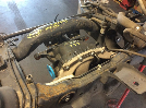
I wanted to retain the two A4LD harnesses located underneath the truck. Using the following method, I will be able to obtain that goal. But first I needed a spare 5-pin switch, which is the one pictured above (Thanks Dan!)

My plan is to use the 5 copper pins, solder on some wire, and then tie that into the 5R55E C113 Grey connector. Doing it this way, when I drop the modified harness into the truck, it will simply plug into the existing electrical, and no splicing underneath the truck is needed. So I cut it half :p:
205034_733094925171_2543709_n.jpg


See, the yellow plastic housing the copper pins is pressed into the steel case, and the edge is then beveled in to hold the plastic housing inside the case. Which is why I cut it in half. At this point, I still needed to get the rest of the casing off, so using a bandsaw, i split it on two sides, and just like a walnut, i got the yellow goodness out.
197609_733094955111_3846926_n.jpg


So now I have access to the 5 copper pins, and can solder on some wire, and thus have converted a switch into a male electrical connector. This should be much easier than trying to cut off the female plug, splice and solder underneath the truck.


And seriously everyone, thanks for all the positive feedback and support. Hopefully I will have an answer for you folks as to whether or not this whole swap will have been worth it on Sunday evening, 4-10-2011. Thanks!


sometimes i question your sanity...


Hopefully you are going to be setting up a wiring diagram now that you have this P/N switch apart. :D

And no problem on the switches. Just glad somebody could use them before they got thrown away.


Hopefully you are going to be setting up a wiring diagram now that you have this P/N switch apart. :D

And no problem on the switches. Just glad somebody could use them before they got thrown away.

Dont worry Dan, I have my finished 'wiring spreadsheet of destiny' sitting at the house right now, but I will need to look tonight at AllData at the 5 pin wiring diagram so I know what pin does what. Will have more photos tonight :D Thanks again Dan for the parts!

Speaking of which, I think I only lack two more peices to this puzzle...two 20 ohm resistors for the a4ld solenoids...


Ok Guys, sorry for delay, I will have more updates tonight :)


Join the Elite Explorers for $20 each year.
Elite Explorer members see no advertisements, no banner ads, no double underlined links,.
Add an avatar, upload photo attachments, and more!
.


The harness is completed!!

Yep, that's right. After 5 months of planning, scouring, scooping, prodding, and pulling, I now have the theoretical 5R55E Conversion Harness built! But how about some photos first? :D

First I went ahead and extended the DLC harness to it's proper length to underneath the steering wheel
200599_733420153411_4975775_n.jpg


Then I started on some of the park / neutral switch. If you remember, I cut that sucker in half and converted it from a switch to a male electrical connector. So I soldered on 5 wires, and BAM, that's done!
216317_734187475691_269938_n.jpg

206872_734188693251_6602037_n.jpg


After that I extended the two transmission connectors (C113 and C118 for technical reference) on the harness. I will probably end up passing these through the transmission tunnel cover with a rubber grommet similar to that of the V6 transfer case wiring harness assembly located under the driver seat.

I also Wired up a momentary contact switch and light (this is temporary) for the O/D Off Function and for testing purposes. After all this was done, I took it outside, laid it all out, and hooked everything up that was going to be inside Blue. That's a lot of wiring! :roll:
205696_734559115921_6213588_n.jpg

215207_734559185781_7576680_n.jpg

You can see the EEC-V pcm sitting towards the back of the photo and the EEC-IV computer towards the front, near the big red plug-looking thing.

Then I had to have my picture taken with this monstrosity...
208452_734559325501_1693707_n.jpg


So all in all, it was a very productive night! Now all that is left, and seriously, this is it, is install the transmission. That's it. After the tranny is stabbed, everything will no simply plug into place and be done with it. Then of course, I still need a radiator :rolleyes:


Back
Top