Reading voltage on inertia switch | Ford Explorer Forums - Serious Explorations

  • Register Today It's free!

Reading voltage on inertia switch

WECALLHERDORA

Active Member
Joined
April 16, 2006
Messages
50
Reaction score
0
City, State
michigan
Year, Model & Trim Level
1994 ltd
I have been told I should use a test light or analog reader to test the power to my inertia switch. I have located the switch, but I am not sure what to do next. any help will be appreciated as I have little knowledge of wiring but am a quick study and can follow directions. there is a pink and black wire and a green and yello wire.


Join the Elite Explorers for $20 each year.
Elite Explorer members see no advertisements, no banner ads, no double underlined links,.
Add an avatar, upload photo attachments, and more!
.


All the inertia switch does is stop a signal that would normally continue on to the fuel pump in the case of a roll over accident.

So all you have to do is jumper the wires (paper clip) then turn your key and listen for the fuel pump to prime (comes on for 1 second when the key is turned to teh on position)
If it comes on your intertia switch wires are getting the signal.
I believe this is a - signal not 12V+ but that is from memory.

are you having problems with your fuel pump coming on?
98% of the time the issue is with the fuse or relay, not the inertia switch.

Good luck!


Yes my fuel pump is not priming and vehicle will not start. I have been advised by others to get a test light and test this switch. I have put in a new relay and no change what else should I be doing?


also I am not sure about jumper the wires. sorry to sound stupid but I need specifics. I know how to jumper the self tester to get CEL codes can you be more specific about how to jumper this switch.


check the fuse?
First bypass the inertia switch
then check for 12V+ at the fuel pump fuse (20 amp, on a 94 its a small blade fuse in the middle of your large under hood fuse box) if that checks out, put the fuse back in and check for 12v+ at the + side of the relay, then check for -, then have somebody turn the key and check for the + signal (switched) getting to the relay.

here's how it works:
You turn key to ON, computer sends a signal to the fuel pump relay to turn the pump on, just for a second.
This signal travels through the inertia switch and out to the relay.
As you know a 4 or 5 prong relay already gets a 12V+ from the battery, in this case from the 20 amp fuse. It also gets a - signal from the power dist box.
SO at the relay you should have 12V+ with no key on, and a healthy ground.
then when you turn the key to ON the switched wire from the computer should power up the relay and the relay will switch and send 12V+ out to the pump.

If your pump still does not come on, check the wiring to the pump, below your brake booster...

If all this fails and the fuse and relay check out, you can test the pump by hooking it up directly to a battery and see if it comes on.


bypass the inertia switch?


I see the fuse but how to check it I am not sure to put what where? I am just a dum girl and need more information on how to do this.


okay the intertia switch just takes power from the wire coming in and sends it to the wire going out, unless your truck is upside down.
So by putting a paper clip in the wiring harness from one wire to the other you are basically eliminating the intertia switch as your problem

Pull the small yellow fuse and look through it, is the metal inside the plastic housing broken? If so your fuse is bad, replace it.
If not, put the fuse back but look where it plugs in and make sure the metal clips the fuse sits in are there and are clean looking.

Now you need a test light or volt meter to check the power signals at the relay wires..


ok I am going right now to look at the fuse. And I have test light but i am not sure about how to use it properly.


fuse is good nothing broken and connectors are clean


bypassing the inertia switch .. wiring harness is at the bottom of the switch correct ? I remove it and run jumper wire from one side to the other side? Sorry again to be so dense but I am very new to all of this.


ok used test light to check for power at fuse and there is power


okay now you have to do the same at the relay

All 4 and 5 prong relays are wired the same so you can do a search online to find out which is which.


RelayWiringGuide.jpg


http://www.rowand.net/Shop/Tech/AllAboutRelays.htm

quick study on automotive relays, should help you diagnose the fuel pump wiring.

if you have power at the fuse and at the relay then the next step is to test at the pump itself (or as close to it as you can get) then if the pump wiring has power and the pump is still not coming on, you need a new pump.
This is very rare IMO, typically the pump will still run, but just not provide enough fuel pressure when they get old/weak

I suspect the relay or wiring to/from it personally.


I have power to the relays. Checked each one. Will do more tomorrow. If I wanted to connect the fuel pump to a battery without dropping the tank how should I connect the wires?


Thank you for all your help today I learned alot and I appreciate it. I wanted to show you something that DeRocha said about the inertia switch, that originally led me to believe this might be the problem. "Observing the Inertia switch is pushed in is step 1... step 2 is actually checking to see if the switch is getting power... You need to get a mult-meter (test light will do) positive or probe end to either switch wire and ground to well ground.. When you turn the key from off to run (don't turn all the way to start) you should see 12v (or probe light on) for 2-3 secs... If so it indicates power is being sent to the pump and a problem exists in the wiring, wire connector (@ rear of gas tank), or fuel pump itself." I tried this after learning how to use the test light and there is no power here. not to dismiss your thoughts with the jumper wire, because if no power goes there anyway the jumper wont make any difference. So I am thinking I should back up from the switch wires and trace the power loss backwards from there. Like I said relays check out is it just wiring in between the 2 or am I completely missing the mark?


when you say the "relays check out".... what do you mean? Assuming you are talking about the fuel pump relay. You have power at the "pull up side" (ie. causing the relay to operate - close the contacts to allow a voltage to flow from one contact to another) and you have voltage on side of the contacts and when operate can find the same voltage on the other. If so then you have a wiring issue from that relay to the switch. If not, then which condition mentioned before doesn't exist?


This may help, it's the diagram for a 4.0 OHV. If yours is not a 4.0 OHV, let me know and I will post the applicable drawing.
1. Our action starts in the upper left hand corner with wire 926. This comes from the EECM and will go low (gnd) for the 1 -2 seconds that the pump primes upon start up.
NOTE: I can post this circuit later if the vehicle in question is a 4.0 OHV.
2. This closes the relay. The flag 'C' is +12 volts and comes from the EEC relay (another drawing)
3. Power comes down through the now closed relay and goes to the inertia switch and the EECM.
4. The +12 volts goes to the fuel pump motor and the pump runs.

Note that this only occurs for the 1-2 seconds that the EECM turns on the pump at start up.

There are a large number of factors and possibilities involved here that would make this a two page dissertation. For example the EECM supplied ground from step 1 that starts this off is available at the VIP test connector. The +12 volt signal that goes to the EECM in step 3 tells the computer whether the relay is working. For the OBD1 systems the error code is 87.

If yours is a 4.0 OHV and it's not raining tomorrow, I'll check some things on my car tomorrow with pictures. Perhaps the drawing will understand some of the other's explanations.
 

Attachments

  • Fuel.JPG
    Fuel.JPG
    59.8 KB · Views: 28,056


If there is no power getting to the inertia switch, it does sound like the relay. If the relay receptacle contacts are accessable, try bypassing the relay function. Have you already swapped the relays, to check the fuel pump relay?

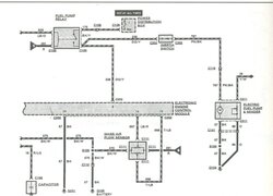
That relay diagram above seems incomplete, or lacking detail. Usually you see four separate terminals, above shows the PCM connected to the main power load circuit. The PCM triggers the load, it doesn't supply it. You should be able to jump power to the wire going to the ineretia switch, but not to the PCM wire.

You can use a pin to jump power to the fuel pump circuit, but you must not accidently touch the terminal which leads to the PCM. The PCM is a low power component, it cannot take any full power on its many ground leads. Only do this if you can be sure to not touch the PCM wire.

The point here is to bypass that PCM ground triggering signal, and make the connection from battery to fuel pump. Note the wire colors above, remove the relay, and see if you can locate the main two terminals.

BTW, when you know that you do have power getting to the fuel pump, you can sometimes hit the bottom side of the fuel tank, and get the pump top trigger. If that happens, the pump is shot. Good luck,


Join the Elite Explorers for $20 each year.
Elite Explorer members see no advertisements, no banner ads, no double underlined links,.
Add an avatar, upload photo attachments, and more!
.


This is very helpful. I would like more info on how to bypass the relay function. I have purchased a new relay and also swapped out relays with no change in funtion.

Also if I remove the relay will the two main terminals show on my tester as having power?


Back
Top