2000StreetRod
Moderator Emeritus
- Joined
- May 26, 2009
- Messages
- 10,597
- Reaction score
- 334
- City, State
- Greenville, SC
- Year, Model & Trim Level
- 00 Sport FI, 03 Ltd V8
Ford recommends changing the PCV valve every 100,000 miles. My Sport has 151,000 miles and I suspected it had the original valve. In my defense, I have only put about 1,000 miles on the vehicle since I purchased it this May. I have been experiencing a loping and rough idle (symptoms of a plugged or restricted PCV valve) for several months (since changing to a high flow air filter) and decided it was time to swap the valve. Having read other forum members' accounts of the difficulty of finding and changing the valve I dreaded the activity.
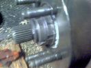
Identifed in the photo below is the PCV valve that is centrally located between the firewall and the lower rear of the upper intake manifold.

While it is not visible in the photo, directly above the valve is a nonsymmetrical "T" fitting that is attached to two hoses going in opposite directions to different ports on the upper intake manifold. Crankcase fumes flow up thru the PCV valve and into the intake manifold to be burned in the cylinders. The photo below shows the hose that connects to the port in the left (driver) side of the intake manifold. There is a similar arrangement on the right side.

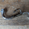
Knowing that it would be difficult to remove the PCV valve, I disconnected the hose connection at each intake port and moved the cruise control cable out of the way. I noticed the remains of a plastic fastener that at one time had held the PCV valve in its intended position. From the passenger side with my left hand I grasped the flared rubber hose end attached to the base of the valve. With my right hand I grasped the "T" and attached hoses. I then twisted, rocked from side to side and pulled until something came apart. Unfortunately, the "T" separated from the top of the valve and the valve remained attached to the flared rubber hose end. I inspected the "T" with hoses assembly shown in the photo below.

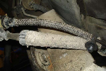
The hose in the area between the red arrows was flattened significantly due to being taught against the rear of the intake manifold. While it's not visible in the photo, there were significant indentations in the hose at the location marked by the green arrow. The photo below is a top view of the "T" and hose assembly (ignore the PCV valve) which came later.

There was significant abrasion damage on the hose at the identified location. While neither hose appeared to leak or be blocked from the damage, I decided hose replacement was warranted.
Identifed in the photo below is the PCV valve that is centrally located between the firewall and the lower rear of the upper intake manifold.
While it is not visible in the photo, directly above the valve is a nonsymmetrical "T" fitting that is attached to two hoses going in opposite directions to different ports on the upper intake manifold. Crankcase fumes flow up thru the PCV valve and into the intake manifold to be burned in the cylinders. The photo below shows the hose that connects to the port in the left (driver) side of the intake manifold. There is a similar arrangement on the right side.
Knowing that it would be difficult to remove the PCV valve, I disconnected the hose connection at each intake port and moved the cruise control cable out of the way. I noticed the remains of a plastic fastener that at one time had held the PCV valve in its intended position. From the passenger side with my left hand I grasped the flared rubber hose end attached to the base of the valve. With my right hand I grasped the "T" and attached hoses. I then twisted, rocked from side to side and pulled until something came apart. Unfortunately, the "T" separated from the top of the valve and the valve remained attached to the flared rubber hose end. I inspected the "T" with hoses assembly shown in the photo below.
The hose in the area between the red arrows was flattened significantly due to being taught against the rear of the intake manifold. While it's not visible in the photo, there were significant indentations in the hose at the location marked by the green arrow. The photo below is a top view of the "T" and hose assembly (ignore the PCV valve) which came later.
There was significant abrasion damage on the hose at the identified location. While neither hose appeared to leak or be blocked from the damage, I decided hose replacement was warranted.