2000StreetRod
Moderator Emeritus
- Joined
- May 26, 2009
- Messages
- 10,597
- Reaction score
- 334
- City, State
- Greenville, SC
- Year, Model & Trim Level
- 00 Sport FI, 03 Ltd V8
Background:
The Ford 4.0L single overhead camshaft (SOHC) V6 engine manufactured in Cologne, Germany was available in the 1997 thru 2010 Ford Explorer and Mercury Mountaineer, 2001 thru 2011 Ford Ranger and Mazda B4000, 2005 thru 2010 Ford Mustang and 2004 thru 2008 Land Rover LR3/Discovery 3. Any SOHC engine requires periodic replacement of the camshaft timing mechanism. The possible mechanisms used to enable the crankshaft to rotate the camshafts are gears, chains and belts. Metal gears would be the most reliable but are not practical due to the distance between the crankshaft and the camshafts. Early dual overhead cam engines incorporated dual row roller chains with tensioner(s) to connect a sprocket mounted on the crankshaft to sprockets mounted on the camshafts. Many modern SOHC engines utilize a timing belt that must be replaced every 70,000 to 100,000 miles. High performance engines incorporate increased valve lift and higher compression ratios. Failure to replace the camshaft timing mechanism at the recommended interval risks timing chain/belt slip or total failure resulting in the pistons colliding with the valves.
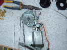
The Cologne SOHC V6 replaced the overhead valve (OHV) V6 camshaft with a jackshaft that transfers crankshaft rotational forces to the left camshaft sprocket at the front of the engine and the right camshaft sprocket at the rear of the engine via multiple chains and tensioners. The primary (crankshaft to jackshaft) timing chain components consist of crankshaft sprocket, jackshaft sprocket, connecting chain, and a chain guide and tensioner as shown in the photo below by White98.

The above photo shows the original style tensioner that has failed.
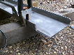
An assembly consisting of a jackshaft sprocket, camshaft sprocket, connecting chain and chain guide constitute a cassette. The camshaft chain is kept taught by a spring loaded hydraulic tensioner utilizing engine oil pressure. A photo of the left cassette is shown below.

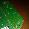
A photo of the right cassette with the metal reinforced tensioner (slack) side is shown below.

The engines in the 4 wheel drive models and a relative few number of 2 wheel drive models incorporated a balance shaft driven by a chain connected to an additional crankshaft sprocket. There is also an associated chain guide and tensioner.
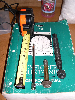
Normally, chain driven overhead camshafts would be more reliable than belt driven overhead camshafts. However, many failures occurred during the first few years of the SOHC V6 engine production. Ford implemented a series of tensioner and guide improvements to increase reliability and recalls to install them. All of the timing chain related improvements were incorporated in the 2002 and later production models. The base of the primary tensioner was strengthened and the number of leaf springs was increased from 3 to 6. The photo below compares the improved and original primary tensioners.

The spring loaded hydraulic tensioners were modified. The camshaft guides constructed of a plastic type material were reinforced with metal. Unfortunately, the traction side of the right guide assembly was never reinforced with metal and can break due to heat and vibration fatigue. Replacement of the right guide requires removal of the engine or the transmission since the guide lower mounting bolt is under the transmission bellhousing between the rear of the engine block and the flywheel/flexplate. Removal of the engine, replacement of the timing chain components, timing of the camshafts and the reinstallation of the engine is a complicated and labor intensive process which performed by a dealer or repair shop may cost more than the market value of the vehicle after repair. A special camshaft timing tool set (OTC 6488) reduces the complexity of the process but is normally not available on a rental basis.
There are well documented procedures available for assembly of the SOHC V6 engine. If anyone needs one just PM me your e-mail address and I will send you a copy. However, I have not found an adequate description of how to remove the timing chain related components. This thread will attempt to provide a SOHC V6 timing chain components removal procedure. It is based on my experience from replacing the timing components in my 2000 Explorer Sport engine and information I have obtained from my Haynes Repair Manual, the Explorer Forum, and other internet resources. The procedure has not been validated and I caution you to use it at your own risk. Some steps should be performed in the order indicated while for others the order may not matter. I will add text and photos as time permits and will attempt to give credit when photos are not my own. I am no expert on this engine and make mistakes like anyone else. I would like to improve the quality of this procedure over time by incorporating your constructive comments/corrections.
The Ford 4.0L single overhead camshaft (SOHC) V6 engine manufactured in Cologne, Germany was available in the 1997 thru 2010 Ford Explorer and Mercury Mountaineer, 2001 thru 2011 Ford Ranger and Mazda B4000, 2005 thru 2010 Ford Mustang and 2004 thru 2008 Land Rover LR3/Discovery 3. Any SOHC engine requires periodic replacement of the camshaft timing mechanism. The possible mechanisms used to enable the crankshaft to rotate the camshafts are gears, chains and belts. Metal gears would be the most reliable but are not practical due to the distance between the crankshaft and the camshafts. Early dual overhead cam engines incorporated dual row roller chains with tensioner(s) to connect a sprocket mounted on the crankshaft to sprockets mounted on the camshafts. Many modern SOHC engines utilize a timing belt that must be replaced every 70,000 to 100,000 miles. High performance engines incorporate increased valve lift and higher compression ratios. Failure to replace the camshaft timing mechanism at the recommended interval risks timing chain/belt slip or total failure resulting in the pistons colliding with the valves.
The Cologne SOHC V6 replaced the overhead valve (OHV) V6 camshaft with a jackshaft that transfers crankshaft rotational forces to the left camshaft sprocket at the front of the engine and the right camshaft sprocket at the rear of the engine via multiple chains and tensioners. The primary (crankshaft to jackshaft) timing chain components consist of crankshaft sprocket, jackshaft sprocket, connecting chain, and a chain guide and tensioner as shown in the photo below by White98.
The above photo shows the original style tensioner that has failed.
An assembly consisting of a jackshaft sprocket, camshaft sprocket, connecting chain and chain guide constitute a cassette. The camshaft chain is kept taught by a spring loaded hydraulic tensioner utilizing engine oil pressure. A photo of the left cassette is shown below.
A photo of the right cassette with the metal reinforced tensioner (slack) side is shown below.
The engines in the 4 wheel drive models and a relative few number of 2 wheel drive models incorporated a balance shaft driven by a chain connected to an additional crankshaft sprocket. There is also an associated chain guide and tensioner.
Normally, chain driven overhead camshafts would be more reliable than belt driven overhead camshafts. However, many failures occurred during the first few years of the SOHC V6 engine production. Ford implemented a series of tensioner and guide improvements to increase reliability and recalls to install them. All of the timing chain related improvements were incorporated in the 2002 and later production models. The base of the primary tensioner was strengthened and the number of leaf springs was increased from 3 to 6. The photo below compares the improved and original primary tensioners.
The spring loaded hydraulic tensioners were modified. The camshaft guides constructed of a plastic type material were reinforced with metal. Unfortunately, the traction side of the right guide assembly was never reinforced with metal and can break due to heat and vibration fatigue. Replacement of the right guide requires removal of the engine or the transmission since the guide lower mounting bolt is under the transmission bellhousing between the rear of the engine block and the flywheel/flexplate. Removal of the engine, replacement of the timing chain components, timing of the camshafts and the reinstallation of the engine is a complicated and labor intensive process which performed by a dealer or repair shop may cost more than the market value of the vehicle after repair. A special camshaft timing tool set (OTC 6488) reduces the complexity of the process but is normally not available on a rental basis.
There are well documented procedures available for assembly of the SOHC V6 engine. If anyone needs one just PM me your e-mail address and I will send you a copy. However, I have not found an adequate description of how to remove the timing chain related components. This thread will attempt to provide a SOHC V6 timing chain components removal procedure. It is based on my experience from replacing the timing components in my 2000 Explorer Sport engine and information I have obtained from my Haynes Repair Manual, the Explorer Forum, and other internet resources. The procedure has not been validated and I caution you to use it at your own risk. Some steps should be performed in the order indicated while for others the order may not matter. I will add text and photos as time permits and will attempt to give credit when photos are not my own. I am no expert on this engine and make mistakes like anyone else. I would like to improve the quality of this procedure over time by incorporating your constructive comments/corrections.