-
Performance Upgrades - Maintenance - Modifications - Problem Solving - Off-Road - Street Trucks.
Covering the Explorer, ST, Sport, Lincoln Aviator, Sport Trac,
Mercury Mountaineer, Mazda Navajo, Ford Ranger, Mazda Pickups, and the Aerostar.
Featuring H.I. - Human Intelligence.
Register Today It's free!
You are using an out of date browser. It may not display this or other websites correctly.
You should upgrade or use an alternative browser.
You should upgrade or use an alternative browser.
Another OHV M90 build
- Thread starter Dono
- Start date
Elite Explorer members see no advertisements, no banner ads, no double underlined links,.
Add an avatar, upload photo attachments, and more!.
jd4242
Explorer Addict
- Joined
- October 15, 2008
- Messages
- 10,790
- Reaction score
- 312
- City, State
- va beach
- Year, Model & Trim Level
- 92explorer&94 ranger
Ya, I spent time reading on he forum. Some conflicting info, but I hope I got it. I also hope fuel will be fine, with no pain. I don't have a vac line from my little pulse corrector thingy to my manifold.
Today, I popped a hole thru my firewall and ran the wideband o2 line, and vac-boost line. I will tap my fuel rail for fuel pressure gauge when I take it off for the new injectors. I sure hope I don't mess up the threading part.
I'd like to get that wideband o2 gauge working just out of curiosity to see what my trucks currently doing for air-fuel ratio.
Im just going to get an aftermarket fuel line "T" and T it right where the in feul line attaches.pretty sure you could do the same.ill have to fine the link and pic,summit sells them.
Elite Explorer members see no advertisements, no banner ads, no double underlined links,.
Add an avatar, upload photo attachments, and more!.
jd4242
Explorer Addict
- Joined
- October 15, 2008
- Messages
- 10,790
- Reaction score
- 312
- City, State
- va beach
- Year, Model & Trim Level
- 92explorer&94 ranger
My fuel rail is round so drilling and tapping it would be pretty hard.ill have to find mine,i have one from my old NOS kit,think it had a female and two males.it split the line so you could get gas for the gas solenoid,it was a wet kit.you just screwed it onto the nipple on the fuel rail then attache the fuel line to one side and the gauge or solenoid line to the other.
rocket 5979
Resident Gearhead
- Joined
- April 22, 2002
- Messages
- 4,017
- Reaction score
- 10
- City, State
- Lake Villa, Illinois
- Year, Model & Trim Level
- '03 XLT 4.6
yea you lost mewe are using a stock fpr.i works by vac,high vac it opens and lowers fuel pressure,low vac or no vac it closes and increases fuel pressure.i didnt understand the pre blower or pre tb stuff either.after the charger where it mounts to the lower intake manifold should see vac and boost right?i would think everything on the other side(the intake side for the blades) would see nothing but vac.i would think at low rpm the air bypass would cause vac and when in high rpms the sc would be causing ALOT of vac.where does the boost gauge mount?i think this is where the stock fpr needs to mount,it needs vac and no vac(boost)
Yes the proper place to tie into boost/vacuum for a boost/vac gauge is post-blower into the lower intake manifold for a roots supercharger setup. At idle and low RPM's the vacuum bypass valve will be swung open with vacuum to allow air to bypass the rotors. Once you increase engine RPM's and start to transition out of vacuum then there is no longer anything to pull the bypass valve open so it closes and only allows the aircharge to go through the blower rotors. Up until this point in time anything post-TB will have been in vacuum. Now once the blower goes into making boost then you will of course have positive pressure in the lower intake manifold post-blower. You should also have no vacuum pre-blower as long as your intake tube system and filter doesn't create drag in airflow coming into the blower.
ok understand this a little better.i would think pre tb would see a little vac at idle and full vac at acceleration?sounds like a stock fpr works like a boost ref fpr,just increases fp in the rail when under boost(no vac) or acceleration
Pre TB means actually in the cold air intake tube that the MAFS is in. You would see zero vacuum here if you took a pressure/vac reading at this location.
Most stock FPR's do not function in boost, but only compensating for fuel pressure in a real vacuum or neutral pressure. They usually don't increase fuel pressure in a 1:1 ratio when the manifold is pressurized above atmospheric. I would really check this if I were you because it probably should ONLY see vacuum and neutral, and not boost. This will of course change the location where you tie into the manifold at from post-blower to pre-blower but post-TB so you see vacuum only while idling or part throttle.
rocket 5979
Resident Gearhead
- Joined
- April 22, 2002
- Messages
- 4,017
- Reaction score
- 10
- City, State
- Lake Villa, Illinois
- Year, Model & Trim Level
- '03 XLT 4.6
Yup, returnless. The fpr is in the gas tank, and on the rail there is some kind of pulse smoothing unit. I've read quite a bit about the returnless system. Lots of confusion around it.
Yes, you have what is called mechanical returnless. Basically think of your fuel system as a return fuel system in every way except that the FPR is located inside the tank with only a single fuel feed line going forward to the rails. Any excess fuel pressure above 43 psi (your stock FP) is immediately bypassed back into the tank by the FPR that is mounted in the stock fuel pump bucket. So since a conventional return system has the FPR loated at the front of the vehicle you will have to have a fuel feed and fuel return line routing from the fuel tank since fuel has to travel all the way to the front of the vehicle before bypassing through the FPR.
rocket 5979
Resident Gearhead
- Joined
- April 22, 2002
- Messages
- 4,017
- Reaction score
- 10
- City, State
- Lake Villa, Illinois
- Year, Model & Trim Level
- '03 XLT 4.6
Ya, I spent time reading on he forum. Some conflicting info, but I hope I got it. I also hope fuel will be fine, with no pain. I don't have a vac line from my little pulse corrector thingy to my manifold.
Today, I popped a hole thru my firewall and ran the wideband o2 line, and vac-boost line. I will tap my fuel rail for fuel pressure gauge when I take it off for the new injectors. I sure hope I don't mess up the threading part.
I'd like to get that wideband o2 gauge working just out of curiosity to see what my trucks currently doing for air-fuel ratio.
You will be totally fine with fuel since you will be running a higher flowing pump and injectors. Most stock pumps will not be able to keep up with the required fuel flow needed by the supercharger. If the pump is too small then you will see fuel pressure start dropping off on the top end. Since you will be installing a bigger pump it will bypass more fuel while the engine doesn't need it because it is capable of flowing more fuel, but it will also be able to keep up with the fuel demands on the top end and not lose fuel pressure even up to redline.
If you aren't very skilled at tapping NPT pipe threads then I would take the rails to someone who is familiar with tapping threads. They can then tap the threads to screw the fitting in and also silver solder it in there so no leaks will occur. Your stock fuel rails are made from pretty thin metal so there isn't much material for the tapped threads to allow for a good seal to the fitting. Make sure that care is taken so the rail doesn't leak.
The other option is to run an QD tee adapter. Get a male QD on one side and a female on the other, with a 1/8" NPT port in the middle. This will connect between the stock fuel rail male quick disconnect and the female quick disconnect on the fuel supply line. Jegs or Summit should have these. EDIT: I just noticed that JD seems to have mentioned something similar in post#242. Something like THIS but you will have to check the O.D. size of your fuel rail male QD nipple.
If those prove to be too much then a third option would be to replace your stock hard plastic fuel rail crossover tube with a soft rubber fuel injection hose and tee into that with a tee that has two hose barb ends equal to the new soft fuel injection line you will be using and the other will have the 1/8" female NPT port you are looking for. Clamp it all down with some fuel injection clamps or some Oetiker clamps and you will be good to go.
jd4242
Explorer Addict
- Joined
- October 15, 2008
- Messages
- 10,790
- Reaction score
- 312
- City, State
- va beach
- Year, Model & Trim Level
- 92explorer&94 ranger
Yep..all depends on what his gauge uses.they make many adapters so i would think a T or simpler would be best.taping the fuel rail i didnt even wanna think about.ill post a pic from my other cars with NOS setup,i luv NOS!!You will be totally fine with fuel since you will be running a higher flowing pump and injectors. Most stock pumps will not be able to keep up with the required fuel flow needed by the supercharger. If the pump is too small then you will see fuel pressure start dropping off on the top end. Since you will be installing a bigger pump it will bypass more fuel while the engine doesn't need it because it is capable of flowing more fuel, but it will also be able to keep up with the fuel demands on the top end and not lose fuel pressure even up to redline.
If you aren't very skilled at tapping NPT pipe threads then I would take the rails to someone who is familiar with tapping threads. They can then tap the threads to screw the fitting in and also silver solder it in there so no leaks will occur. Your stock fuel rails are made from pretty thin metal so there isn't much material for the tapped threads to allow for a good seal to the fitting. Make sure that care is taken so the rail doesn't leak.
The other option is to run an QD tee adapter. Get a male QD on one side and a female on the other, with a 1/8" NPT port in the middle. This will connect between the stock fuel rail male quick disconnect and the female quick disconnect on the fuel supply line. Jegs or Summit should have these. EDIT: I just noticed that JD seems to have mentioned something similar in post#242. Something like THIS but you will have to check the O.D. size of your fuel rail male QD nipple.
If those prove to be too much then a third option would be to replace your stock hard plastic fuel rail crossover tube with a soft rubber fuel injection hose and tee into that with a tee that has two hose barb ends equal to the new soft fuel injection line you will be using and the other will have the 1/8" female NPT port you are looking for. Clamp it all down with some fuel injection clamps or some Oetiker clamps and you will be good to go.
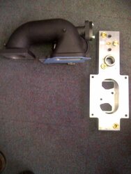
i built this motor for NOS but the one off 3800 build and sound,im all inhaharocket 5979
Resident Gearhead
- Joined
- April 22, 2002
- Messages
- 4,017
- Reaction score
- 10
- City, State
- Lake Villa, Illinois
- Year, Model & Trim Level
- '03 XLT 4.6
Yep..all depends on what his gauge uses.they make many adapters so i would think a T or simpler would be best.taping the fuel rail i didnt even wanna think about.ill post a pic from my other cars with NOS setup,i luv NOS!!
Since I assume he is using an electronic FP gauge it most likely has a 1/8" NPT male thread on the end of the FP sensor itself. Not much that a trip to Jegs and maybe the hardware store cannot handle.
jd4242
Explorer Addict
- Joined
- October 15, 2008
- Messages
- 10,790
- Reaction score
- 312
- City, State
- va beach
- Year, Model & Trim Level
- 92explorer&94 ranger
Since I assume he is using an electronic FP gauge it most likely has a 1/8" NPT male thread on the end of the FP sensor itself. Not much that a trip to Jegs and maybe the hardware store cannot handle.
Yep..i have seen some with a male end,rare but who knows!!never kno about the lower end line of gauges, no disrespect im running prospect gauges
gota throw the disclaimer in for others,...some newbies wanna try and call you out when they see info from some post.rocket 5979
Resident Gearhead
- Joined
- April 22, 2002
- Messages
- 4,017
- Reaction score
- 10
- City, State
- Lake Villa, Illinois
- Year, Model & Trim Level
- '03 XLT 4.6
Yep..i have seen some with a male end,rare but who knows!!
It is the opposite of rare. Almost all of the electronic gauges pressure sensor are a male 1/8" NPT thread.- Joined
- February 18, 2009
- Messages
- 5,335
- Reaction score
- 619
- City, State
- Winnipeg, Manitoba
- Year, Model & Trim Level
- 04 Mustang GT
Yes, the fuel pressure sending unit has a 1/8 ntp male on it. I wish I knew the size of my current fuel system attachment at the fuel rail. A tee would be really easy.
I'll have to look into that part of it. I like easy.
I'll have to look into that part of it. I like easy.
jd4242
Explorer Addict
- Joined
- October 15, 2008
- Messages
- 10,790
- Reaction score
- 312
- City, State
- va beach
- Year, Model & Trim Level
- 92explorer&94 ranger
Yep ive seen alot of crap in my street racing days..ive been a all motor and NOS guy but ive seen most kits include a male to male adapter but seen then with just female.my charger has a male nipple for boost gauge for ecm stock on the side of it but the hole is not drilled in my lower plate for it to work.might drill it through when i re gasket match my lower mount to my IC
EDIT!!sorry my charger has a female.just checked
- Joined
- February 18, 2009
- Messages
- 5,335
- Reaction score
- 619
- City, State
- Winnipeg, Manitoba
- Year, Model & Trim Level
- 04 Mustang GT
Wideband o2 is live. Calibration was a bit of a pain. On the innovate model, you have to pull the sensor out of the exhaust to calibrate it. Its done, and appears to be working.
Currently my A/F ratio is between 9 and 10.4. 10.4 is the ratio at WOT. 14 is optimum, correct?
I just tried moving on the leaner side using my SCT. Im interested to see if I can see a change on the gauge.
Also, I sent James a test data log file, just so he can confirm that he see's the Wideband O2 analog serial input going in to the laptop. At least this way, I can confirm logging is working before I have a vehicle that won't run, and James can't see whats happening.
- Joined
- February 18, 2009
- Messages
- 5,335
- Reaction score
- 619
- City, State
- Winnipeg, Manitoba
- Year, Model & Trim Level
- 04 Mustang GT
More guessing after reading. It looks like target a/f ratio would be around 12 to 13. 14 is pretty aggressive.
I can see how James is guessing when you send him a list of mods and expect him to magically hit the perfect air fuel ratio with a tune. Go on the safe side, and mileage isnt as good as it could be. Go too lean, and blow a clients motor up. I'd be afraid to make any tuning changes without a datalog and seeing the air/fuel ratio.
I can see how James is guessing when you send him a list of mods and expect him to magically hit the perfect air fuel ratio with a tune. Go on the safe side, and mileage isnt as good as it could be. Go too lean, and blow a clients motor up. I'd be afraid to make any tuning changes without a datalog and seeing the air/fuel ratio.
jd4242
Explorer Addict
- Joined
- October 15, 2008
- Messages
- 10,790
- Reaction score
- 312
- City, State
- va beach
- Year, Model & Trim Level
- 92explorer&94 ranger
More guessing after reading. It looks like target a/f ratio would be around 12 to 13. 14 is pretty aggressive.
I can see how James is guessing when you send him a list of mods and expect him to magically hit the perfect air fuel ratio with a tune. Go on the safe side, and mileage isnt as good as it could be. Go too lean, and blow a clients motor up. I'd be afraid to make any tuning changes without a datalog and seeing the air/fuel ratio.
Depends if your talking NA or FI.your make more power on the leaner side.i ran 12.5 but was running rich witch is around where i wanna run after the sc.
jd4242
Explorer Addict
- Joined
- October 15, 2008
- Messages
- 10,790
- Reaction score
- 312
- City, State
- va beach
- Year, Model & Trim Level
- 92explorer&94 ranger
well looks like i wasnt that rich epically considering im higher compression.id like to get a little richer after the sc
http://autospeed.com/cms/title_Tuning-AirFuel-Ratios/A_1595/article.html
http://autospeed.com/cms/title_Tuning-AirFuel-Ratios/A_1595/article.html
rocket 5979
Resident Gearhead
- Joined
- April 22, 2002
- Messages
- 4,017
- Reaction score
- 10
- City, State
- Lake Villa, Illinois
- Year, Model & Trim Level
- '03 XLT 4.6
Wideband o2 is live. Calibration was a bit of a pain. On the innovate model, you have to pull the sensor out of the exhaust to calibrate it. Its done, and appears to be working.
Currently my A/F ratio is between 9 and 10.4. 10.4 is the ratio at WOT. 14 is optimum, correct?
I just tried moving on the leaner side using my SCT. Im interested to see if I can see a change on the gauge.
Also, I sent James a test data log file, just so he can confirm that he see's the Wideband O2 analog serial input going in to the laptop. At least this way, I can confirm logging is working before I have a vehicle that won't run, and James can't see whats happening.
At idle and part throttle your AFR should switch around 14.64 which is due to the ECU being in closed loop mode where it pulls AFR data from the stock front narrowband O2 sensors to target stoich. For WOT you want to see it a little more rich in the middle 12's for n/a vehicle and middle to low 11's in a force induced one.
Elite Explorer members see no advertisements, no banner ads, no double underlined links,.
Add an avatar, upload photo attachments, and more!.
- Joined
- February 18, 2009
- Messages
- 5,335
- Reaction score
- 619
- City, State
- Winnipeg, Manitoba
- Year, Model & Trim Level
- 04 Mustang GT
I've been back and fourth with James on the whole datalog thing.
I was getting readings that made no sense.
Even the gauge showing A/F ratio of around 10 no matter what I did with the throttle made no sense.
It turns out I made a wiring error. I wired the gauge to the wrong analog input. I checked my wiring this morning on the way to work, and found the error. Then I get to work, and had an email from James asking me to check which analog input the gauge was on. Im impressed.
Anyway, the gauge now reads an a/f ratio in the low 14's typically. At WOT, I'm at 13.7. I'll get another datalog and send it to James today for review.
I want to make sure I know what I'm doing during the tuning period after the M90 install, as my truck might not even be drivable until I get a new tune. Without correct information to James, there is nothing he can do.
Featured images


Featured images
Similar Threads
- Article
- Replies
- 295
- Views
- 36,529
- Replies
- 53
- Views
- 27,001
- Replies
- 787
- Views
- 131,744
- Replies
- 1,253
- Views
- 196,928
- Replies
- 14
- Views
- 2,494
- Article
- Replies
- 79
- Views
- 42,532