PlatinumOwner
Well-Known Member
- Joined
- March 6, 2016
- Messages
- 478
- Reaction score
- 150
- City, State
- US
- Year, Model & Trim Level
- 2016 Explorer Platinum
This post will detail the modification, flashing, and bezel removal to convert the 16-19 Platinum Instrument Panel Clusters to a full-screen display(no longer a hybrid digital/analog IPC). This mod was made possible with custom designed firmware graphics by Pawel and a 3D-printed bezel by Thierry on the FORD UPGRADES Facebook group. For custom firmware, please contact Pawel on the FORD UPGRADES group.
Below: a modified Mondeo IPC

Below: Custom Explorer firmware (preview is in km/kmh)

1) Firmware modification
EJ7T-14C025-AA (Secondary Bootloader)
JB5T-14C026-EB (Software)
JB5T-14C026-FB (Software)
JB5T-14C088-EB (Graphics)
JB5T-14C088-FB (Main Graphics file)
The main graphics file can be modified using the web interface at PimpMyFord but I recommend contacting Pawel for a custom firmware.
2) Firmware flashing
As long as you have the latest firmware installed, only the SBL and main graphics file need to be selected when flashing. This can be done with UCDS or FORScan Beta.
EJ7T-14C025-AA
JB5T-14C088-FB(modified graphics file)
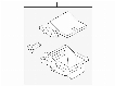
3) Changing the IPC bezel
Remove the IPC. First lift off the flap then pry the bezel forward with a nylon pry tool. There are two snaps at the top and two at the bottom. When you pull the bezel out you must disconnect the temp sensor in the lower right side.
Remove the IPC and disconnect the single cable on the back.

Note: Temperature sensor connector in lower right

Remove the Torx T15 screws and carefully un-snap the front of the display. Unscrew the T10 screws from the back of the display, remove the shielding, then disconnect the ribbon cable for LED lighting of the numbers. Unscrew the T10 screws from the front of the display and replace with the new bezel. Re-assemble the display - be sure to use compressed air to keep all dust out of the enclosure.


4) Final product


(without bezel)


Below: a modified Mondeo IPC
Below: Custom Explorer firmware (preview is in km/kmh)
1) Firmware modification
EJ7T-14C025-AA (Secondary Bootloader)
JB5T-14C026-EB (Software)
JB5T-14C026-FB (Software)
JB5T-14C088-EB (Graphics)
JB5T-14C088-FB (Main Graphics file)
The main graphics file can be modified using the web interface at PimpMyFord but I recommend contacting Pawel for a custom firmware.
2) Firmware flashing
As long as you have the latest firmware installed, only the SBL and main graphics file need to be selected when flashing. This can be done with UCDS or FORScan Beta.
EJ7T-14C025-AA
JB5T-14C088-FB(modified graphics file)
3) Changing the IPC bezel
Remove the IPC. First lift off the flap then pry the bezel forward with a nylon pry tool. There are two snaps at the top and two at the bottom. When you pull the bezel out you must disconnect the temp sensor in the lower right side.
Remove the IPC and disconnect the single cable on the back.
Note: Temperature sensor connector in lower right
Remove the Torx T15 screws and carefully un-snap the front of the display. Unscrew the T10 screws from the back of the display, remove the shielding, then disconnect the ribbon cable for LED lighting of the numbers. Unscrew the T10 screws from the front of the display and replace with the new bezel. Re-assemble the display - be sure to use compressed air to keep all dust out of the enclosure.
4) Final product
(without bezel)