-
Performance Upgrades - Maintenance - Modifications - Problem Solving - Off-Road - Street Trucks.
Covering the Explorer, ST, Sport, Lincoln Aviator, Sport Trac,
Mercury Mountaineer, Mazda Navajo, Ford Ranger, Mazda Pickups, and the Aerostar.
Featuring H.I. - Human Intelligence.
Register Today It's free!
- Forums
- Generation Specific Forums
- 1995 - 2001 Explorer Ranger Merc. 2nd Generation
- Stock 1995 - 2001 Explorers
You are using an out of date browser. It may not display this or other websites correctly.
You should upgrade or use an alternative browser.
You should upgrade or use an alternative browser.
Any cam allignment pics? 4.0l sohc
- Thread starter McSlug
- Start date
Elite Explorer members see no advertisements, no banner ads, no double underlined links,.
Add an avatar, upload photo attachments, and more!.
2000StreetRod
Moderator Emeritus
- Joined
- May 26, 2009
- Messages
- 10,597
- Reaction score
- 334
- City, State
- Greenville, SC
- Year, Model & Trim Level
- 00 Sport FI, 03 Ltd V8
Right camshaft end
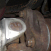
The following caption and photo was posted by CDW6212R:
"Okay, check out this picture of my engine just before I timed it. This picture below shows the right head camshaft end. Notice the two slots in the end of the cam. They are offset to the lower side. The special cam tool engages those and forces the cam to locate those two slots in parallel to the surface of the valve cover rail. Regards, Don"

Unfortunately, the cam bearing cap hides the cam lobes in the photo. It is possible to tighten the cam sprocket bolt 180 degrees off with the tool in alignment.
The following caption and photo was posted by tmh6202:
"Hey Don,
I think it is also worth mentioning that even though you use the tools, only one head can be done at a time. BUT, both the primary chain and front cassette have to be off/out at the same time as the left cassette chain is behind the primary chain. The biggest thing to make certain you do is to keep the cam sensor nub in the proper place in relation to the head. This can change even if you use the OTC6488 tool kit to hold the rear cam in place. The tension from the valve springs will cause the cam to rotate somewhat. I was victim of this during my rebuild. Got it back together, tunred it over, sounded ok but would not catch and run. We took the valve covers off and when compared to before pictures and diagrams, we realized that the flat spot was on the bottom of the cam, 180 degrees off. OOPS! It pays to take pictures and follow directions! The flat spot in the picture below is the opposite side of the cam that needs to be up at installation/tightening of the cassette to cam bolt. The opposite side has a flat spot with a nub that sticks up to "trip" the sensor. I cannot locate a photo of that, but I have not looked at everything I have yet. I will scan a diagram from the instructions tomorrow and post it for those who need it.
Good luck everyone! Mine is still running strong and QUIET!
Todd"

I've seen another photo of the lobes in the correct position but haven't been able to find it yet.
The following caption and photo was posted by CDW6212R:
"Okay, check out this picture of my engine just before I timed it. This picture below shows the right head camshaft end. Notice the two slots in the end of the cam. They are offset to the lower side. The special cam tool engages those and forces the cam to locate those two slots in parallel to the surface of the valve cover rail. Regards, Don"
Unfortunately, the cam bearing cap hides the cam lobes in the photo. It is possible to tighten the cam sprocket bolt 180 degrees off with the tool in alignment.
The following caption and photo was posted by tmh6202:
"Hey Don,
I think it is also worth mentioning that even though you use the tools, only one head can be done at a time. BUT, both the primary chain and front cassette have to be off/out at the same time as the left cassette chain is behind the primary chain. The biggest thing to make certain you do is to keep the cam sensor nub in the proper place in relation to the head. This can change even if you use the OTC6488 tool kit to hold the rear cam in place. The tension from the valve springs will cause the cam to rotate somewhat. I was victim of this during my rebuild. Got it back together, tunred it over, sounded ok but would not catch and run. We took the valve covers off and when compared to before pictures and diagrams, we realized that the flat spot was on the bottom of the cam, 180 degrees off. OOPS! It pays to take pictures and follow directions! The flat spot in the picture below is the opposite side of the cam that needs to be up at installation/tightening of the cassette to cam bolt. The opposite side has a flat spot with a nub that sticks up to "trip" the sensor. I cannot locate a photo of that, but I have not looked at everything I have yet. I will scan a diagram from the instructions tomorrow and post it for those who need it.
Good luck everyone! Mine is still running strong and QUIET!
Todd"
I've seen another photo of the lobes in the correct position but haven't been able to find it yet.
2000StreetRod
Moderator Emeritus
- Joined
- May 26, 2009
- Messages
- 10,597
- Reaction score
- 334
- City, State
- Greenville, SC
- Year, Model & Trim Level
- 00 Sport FI, 03 Ltd V8
More alignment data
This is from another helpful post by Don, CDW6212R:
"Set the cams close to TDC in the heads before bolting them down, and have the engine at TDC then also. You can't spin the cams around after they are on the engine to get them to TDC, the valves would hit pistons. That was my point, all three have to be very near to TDC when they go together.
The TDC tools make it very easy to locate TDC for each cam. I take it you will have each head complete from a shop. You need to rotate each cam until the one tool lines up with the two slots on the cam.
One end of each cam has a bolt and the chain sprocket, call that the front end of the cam. The back end has nothing except two slots cut into it. Those are the timing slots, the one special tool lines up with those slots. You don't have to place the tool in it's holder and bolt it down to the head(valve cover holes).
The slots need to be parallel with the edge of the valve cover rail(draw a line through them), and nearer to the head(I'm trying to remember), instead of farther away from the head. I should have a picture somewhere.
Place each cam like that and then they will be close enough to bolt on. They won't move too far from there that they will put a valve into a piston."
In a few days I should be able to take some photos showing the cam lobes as timed by the factory before my dissassembly. Just remember that the timing tool assumes #1 piston is in compression and at top dead center. That means the cam lobes for cylinder #1 should not be depressing either valve. I believe it also means that the camshaft position sensor protrusion on the other bank should be above the cam.
2000StreetRod
Moderator Emeritus
- Joined
- May 26, 2009
- Messages
- 10,597
- Reaction score
- 334
- City, State
- Greenville, SC
- Year, Model & Trim Level
- 00 Sport FI, 03 Ltd V8
Timing camshafts with caliper
I'm going to try and determine if it is possible to time the camshafts by using a caliper and a flat metal strip/block. The camshaft timing tool positions the notches in the end of the camshaft parallel to the valve cover mating surface of the head and prevents the camshaft from rotating while the sprocket bolt is torqued. The crankshaft timing tool keeps the crankshaft with piston #1 at top dead center (on compression stroke) while each camshaft is aligned. A flat metal strip/block could be positioned on the valve cover mating surface of the head and the perpendicular distance between it and each notch can be equalized by comparing caliper measurements. Some means (such as grasping the camshaft between lobes with locking pliers wedging them against the head) would be required to keep the camshaft from changing position while the sprocket is torqued (62 ft-lbs).
I'm going to try and determine if it is possible to time the camshafts by using a caliper and a flat metal strip/block. The camshaft timing tool positions the notches in the end of the camshaft parallel to the valve cover mating surface of the head and prevents the camshaft from rotating while the sprocket bolt is torqued. The crankshaft timing tool keeps the crankshaft with piston #1 at top dead center (on compression stroke) while each camshaft is aligned. A flat metal strip/block could be positioned on the valve cover mating surface of the head and the perpendicular distance between it and each notch can be equalized by comparing caliper measurements. Some means (such as grasping the camshaft between lobes with locking pliers wedging them against the head) would be required to keep the camshaft from changing position while the sprocket is torqued (62 ft-lbs).
McSlug
Well-Known Member
- Joined
- October 22, 2008
- Messages
- 153
- Reaction score
- 1
- City, State
- Perth Western Australia
- Year, Model & Trim Level
- 98 Explorer
Cam Locking
I have thought of doing what you mentioned to lock the cams. We also were thinking about unbolting one of the cam main caps and bolting it down with a leather strip.
My problem is that I was replacing the left cassette and we rocked the cam to a neutral position to stop it from spinning under pressure but the lack of tension on the jackshaft chain caused the right side to jump. Now the right side is out with the left side and the crank. So I'm hoping to get it close by eye and then time it to avoid piston collision as you can bend valves by hand turning.
steven p nodler
New Member
- Joined
- July 31, 2011
- Messages
- 4
- Reaction score
- 0
- Year, Model & Trim Level
- 2001 ranger xlt 4.0 sohc
i need to know when im settig my cams with the allignment tools when bolted to the head should allignment notches allow the toolto sit flush on both heads while at tdc or am i out of time 1 side sits flush 1 side doesn,tas of now am i out
2000StreetRod
Moderator Emeritus
- Joined
- May 26, 2009
- Messages
- 10,597
- Reaction score
- 334
- City, State
- Greenville, SC
- Year, Model & Trim Level
- 00 Sport FI, 03 Ltd V8
Correct alignment
The timing slot for each cam should be below the center axis of the camshaft and parallel to head surface that the valve cover mounts to. Sounds to me like one of your camshafts is 180 degrees off. When #1 cylinder piston is at TDC on the compression stroke the nub for the camshaft position sensor should be above the center of the camshaft. See some of my helpful threads for photos.
i need to know when im settig my cams with the allignment tools when bolted to the head should allignment notches allow the toolto sit flush on both heads while at tdc or am i out of time 1 side sits flush 1 side doesn,tas of now am i out
The timing slot for each cam should be below the center axis of the camshaft and parallel to head surface that the valve cover mounts to. Sounds to me like one of your camshafts is 180 degrees off. When #1 cylinder piston is at TDC on the compression stroke the nub for the camshaft position sensor should be above the center of the camshaft. See some of my helpful threads for photos.
steven p nodler
New Member
- Joined
- July 31, 2011
- Messages
- 4
- Reaction score
- 0
- Year, Model & Trim Level
- 2001 ranger xlt 4.0 sohc
i was wondering i set both cams on my ranger all positions seem to b in correct place so i wanted to check my harmonic balancer it has a little movement not much is it mormal or should it be solid tight with no movement i can move it bout 1/4 turn looks like my chain flexes
2000StreetRod
Moderator Emeritus
- Joined
- May 26, 2009
- Messages
- 10,597
- Reaction score
- 334
- City, State
- Greenville, SC
- Year, Model & Trim Level
- 00 Sport FI, 03 Ltd V8
excessive play
A quarter turn (90 degrees) of harmonic balancer movement is excessive if the OTC 6488 tool set is installed correctly. There is a little play in the crankshaft to jackshaft chain due to the primary tensioner. If the precision tensioner tool is installed in place of the hydraulic tensioner there should be no play in the camshaft chain on the side being aligned. Are you following the instructions for timing the camshafts with the tool set?
i was wondering i set both cams on my ranger all positions seem to b in correct place so i wanted to check my harmonic balancer it has a little movement not much is it mormal or should it be solid tight with no movement i can move it bout 1/4 turn looks like my chain flexes
A quarter turn (90 degrees) of harmonic balancer movement is excessive if the OTC 6488 tool set is installed correctly. There is a little play in the crankshaft to jackshaft chain due to the primary tensioner. If the precision tensioner tool is installed in place of the hydraulic tensioner there should be no play in the camshaft chain on the side being aligned. Are you following the instructions for timing the camshafts with the tool set?
steven p nodler
New Member
- Joined
- July 31, 2011
- Messages
- 4
- Reaction score
- 0
- Year, Model & Trim Level
- 2001 ranger xlt 4.0 sohc
A quarter turn (90 degrees) of harmonic balancer movement is excessive if the OTC 6488 tool set is installed correctly. There is a little play in the crankshaft to jackshaft chain due to the primary tensioner. If the precision tensioner tool is installed in place of the hydraulic tensioner there should be no play in the camshaft chain on the side being aligned. Are you following the instructions for timing the camshafts with the tool set?
ty for the info it has been very helpful i did not have the tension tool 1st time out. so i started it and it runs with a Missing shutter no noise i shuter down re=read haYNES MANUAL AND REALIZEDI DIDNT FOLLOW PROCEEDURE with tension tool DUHH felt stupid lol but i think i got it now gonna test start again in a few days i hope thanks again oh by the way this is my first time rebuilding a engine ill keep ya updated thanks a million

2000StreetRod
Moderator Emeritus
- Joined
- May 26, 2009
- Messages
- 10,597
- Reaction score
- 334
- City, State
- Greenville, SC
- Year, Model & Trim Level
- 00 Sport FI, 03 Ltd V8
Jefe the Gorilla
Member
- Joined
- July 26, 2011
- Messages
- 10
- Reaction score
- 0
- City, State
- Phoenix, Az
- Year, Model & Trim Level
- '04 Sport-Trac XLT
timing position after heads installed?
I just installed my heads and read the part in the manual that says i need this stupid tool just to set the cams. I know that there's another way so after looking at your posts I have a couple questions: So what you guys are saying is that I need to position the cam with the notches parallel to the cover flange (as seen in the top photo). But if i rotate it too far it may drag the valves across the pistons? If this is true then why cant I just remove the olt in the cam gear and set it aside (supported of course). then loosen the cam holder bolts, place the cam in the proper position (while supporting it from turning), and then tighten it down evenly till seated properly. In my world I believe the cam should press down the valves according to the position and then I can bolt up the cam gear and all should be right in the world. It sounds easy enough but I am wondering why it hasnt been tried before or if it has why it wasn't successful.
I would still love to see a good pic of the cam position of both heads. are they both set the same? I ask cause TDC for #1 is also the tdc for #5 I believe (non compression stroke). The rest of the previous info has been very helpful though. especially since the guys at Ford only want to get me in their shop so they can charge me $1500 on some b/s story instead of being helpful and telling me where to set the cams or at least renting me the tools to do it myself! Where have you guys gotten the tools from?
2000StreetRod
Moderator Emeritus
- Joined
- May 26, 2009
- Messages
- 10,597
- Reaction score
- 334
- City, State
- Greenville, SC
- Year, Model & Trim Level
- 00 Sport FI, 03 Ltd V8
Removing the camshaft
Removing and reinstalling the camshaft without first removing the cam followers is a risky process. The camshaft can bind during installation if the followers are in place and the camshaft bearing cap can break. Since the camshaft has no bearing inserts a broken bearing cap may necessitate purchasing another head. This has happened to at least one forum member. Unfortunately, it takes a special tool to compress the valves on the SOHC V6 to remove and reinstall the cam followers. I have removed and reinstalled both camshafts without first removing the cam followers but I was extremely careful.
When the #1 piston is at TDC the timing slots on both camshafts should be below the axis of the camshaft and parallel to the head surface that mounts to the valve covers. It is difficult to see the slot on the left camshaft when the engine is installed because it is close to the firewall. The OTC 6488 timing tool kit allows accurate camshaft timing with the engine in the vehicle. You can often find one on eBay for about $150. I have timed the camshafts without the tool set but it is risky and I had the engine out of the vehicle. There is more information and photos on timing the SOHC V6 in my helpful threads.
Since you already have the heads installed you have to get the camshafts into position without damaging the valves by being struck by the pistons. You should be able to watch the camshaft lobes to determine when the valves are extended and monitor the piston positions to avoid a piston being at TDC when a valve is fully extended. The firing order is 1-4-2-5-3-6 so yes when #1 is in compression at TDC #5 should be at TDC on the exhaust stroke. Usually when the timing chain slips when the engine is running the exhaust valves are damaged before the intake valves. If you're very careful you should be able to achieve the correct positions without removing the camshafts. Be sure not to force anything if you detect any binding while trying to position the camshafts.
Jefe the Gorilla
Member
- Joined
- July 26, 2011
- Messages
- 10
- Reaction score
- 0
- City, State
- Phoenix, Az
- Year, Model & Trim Level
- '04 Sport-Trac XLT
Yeah I hear ya! I dont really have the time to wait for the tools to come in so Im gonna give it a try and be very carefull. I guess we'll see how it goes. If nothing else I can always remove the heads again and do it with them off the engine right? i just dont want to restretch the bolts. how many times you think I can reuse them? The bolts i mean.
Jefe the Gorilla
Member
- Joined
- July 26, 2011
- Messages
- 10
- Reaction score
- 0
- City, State
- Phoenix, Az
- Year, Model & Trim Level
- '04 Sport-Trac XLT
Well I removed the bearing caps as I stated before. then i turned the cam to the angle specified earlier in the thread. using a crescent wrench to hold it in position I slowly and evenly tightened the cam caps to 53.5 in/lbs (with oil tube removed for now). Then leaving the crescent wrench in place as an opposing torque lever I bolted up the cam gear to the specified torque of 62 ft/lbs (or balls tight since dial faced away from me). then I screwed in the hydraulic tensioner and removed the crescent wrench. next i removed the three bolts that hold down the oil tube, reinstalled the oil tube, torqued the three bolts back to 53.5 in/lbs and continued onto second stage torque (132-150 in/lbs) in sequence from 1-8 (I split the middle at 141 in/lbs). I slowly rotated the engine one complete revolution to check for binding and had none so I repeated the same process for the drivers side head. I used the same criteria for this head and continued in the same fashion. This head was much easier due to the valves were only slightly engaged at the TDC position. I have tried to post the pix below in order for good reference.


So far after setting the cams i have rotated the engine three times with no binding. In fact the engine turned over very easily (no spark plugs in) so I guess its all set right but got my fingers crossed till I test drive it. The yellow arrow in the lower pics is there to indicate the position of the tab on the cam in order to get the proper position where the slot at the rear is parallel to the upper head flange (where valve cover bolts to). I used the cam from damaged head as a guide since it is hard to see with the cam installed. hope this helps as much as everyones info has helped me!
So far after setting the cams i have rotated the engine three times with no binding. In fact the engine turned over very easily (no spark plugs in) so I guess its all set right but got my fingers crossed till I test drive it. The yellow arrow in the lower pics is there to indicate the position of the tab on the cam in order to get the proper position where the slot at the rear is parallel to the upper head flange (where valve cover bolts to). I used the cam from damaged head as a guide since it is hard to see with the cam installed. hope this helps as much as everyones info has helped me!
2000StreetRod
Moderator Emeritus
- Joined
- May 26, 2009
- Messages
- 10,597
- Reaction score
- 334
- City, State
- Greenville, SC
- Year, Model & Trim Level
- 00 Sport FI, 03 Ltd V8
looks good
The positions of the camshafts looks good. I hope you attempted to get the slots as parallel to the heads as possible because one degree of camshaft rotation represents two degrees of crankshaft rotation. However, one or two degrees of camshaft error should not have any significant performance degradation. I would not have used the wrench on the cam lobe to hold it in place because it could damage the lobe surface. The head bolts are torque-to-yield and should not be reused but some members have done it and not reported problems. Hopefully, you tightened the sprocket retaining bolt to at least 62 ft-lbs since that's all that keeps the camshaft from slipping. A click type torque wrench won't make it any easier since most don't click when tightening counter-clockwise. Good luck with the engine start.
The positions of the camshafts looks good. I hope you attempted to get the slots as parallel to the heads as possible because one degree of camshaft rotation represents two degrees of crankshaft rotation. However, one or two degrees of camshaft error should not have any significant performance degradation. I would not have used the wrench on the cam lobe to hold it in place because it could damage the lobe surface. The head bolts are torque-to-yield and should not be reused but some members have done it and not reported problems. Hopefully, you tightened the sprocket retaining bolt to at least 62 ft-lbs since that's all that keeps the camshaft from slipping. A click type torque wrench won't make it any easier since most don't click when tightening counter-clockwise. Good luck with the engine start.
Jefe the Gorilla
Member
- Joined
- July 26, 2011
- Messages
- 10
- Reaction score
- 0
- City, State
- Phoenix, Az
- Year, Model & Trim Level
- '04 Sport-Trac XLT
Well 99% done as of 30 minutes ago. no no no no! You got me all wrong. I only used the wrench on the area that is flattened for the wrench to be used not on the actual lobe. Just like the area where the yellow arrow points to. Alot of overhead cams come with these in order to do what I did and have a place to turn the cam. I used them on on many toyota engines in the past. I would not even attempt to put it on the lobe due to its precision surface. I have an old school DIAL torque wrench so I couldnt see the face. I tried to use an inspection mirror but it would not cooperate so I jst tried to peer over while holding the other wrench. I know I got it close but i think i went a lil over. I wasnt too sure about the positsion of the driver side cam cause there were no actual pics to go from. but after I checked the degrees on the lobes I could tell it was close if not right. I used to do alot of torque to yield bolts in the Navy and still have my strain gauge but I am still leary anytime i use bolts like that over again. just gotta buy a new oil filter in the morning and add new oil and I think she's ready for a test drive. not gonna feel safe till i drive it for a week with no problems but hopefully all goes well. wish me luck!
steven p nodler
New Member
- Joined
- July 31, 2011
- Messages
- 4
- Reaction score
- 0
- Year, Model & Trim Level
- 2001 ranger xlt 4.0 sohc
thanks for the pics and info finished up truck almost except 4 the cosmetic stuff but she runs great ty my peeps for all the help now im got the rebuild fever thanks a million steve!
jeffrotech
New Member
- Joined
- February 15, 2012
- Messages
- 1
- Reaction score
- 0
- City, State
- Greenwood Lake, NY
- Year, Model & Trim Level
- 2002 Ford Explorer
crank key way orientation
I think it would be important to note the position of the crank at this point.
With the cams in the correct position (as pictured in the previous posts, and level with the cylinder head surface), and of course with cylinder #1 on compression, the crank keyway looks to be perfectly at 12:00.
Can anyone confirm this?
Thanks!
Elite Explorer members see no advertisements, no banner ads, no double underlined links,.
Add an avatar, upload photo attachments, and more!.
2000StreetRod
Moderator Emeritus
- Joined
- May 26, 2009
- Messages
- 10,597
- Reaction score
- 334
- City, State
- Greenville, SC
- Year, Model & Trim Level
- 00 Sport FI, 03 Ltd V8
TDC & crank key way
The crank key way is at the twelve o'clock position any time the #1 piston is at TDC (compression or exhaust stroke).
The crank key way is at the twelve o'clock position any time the #1 piston is at TDC (compression or exhaust stroke).
Featured images


Featured images
Similar Threads
- Replies
- 4
- Views
- 4,717
- Replies
- 2
- Views
- 909
- Replies
- 44
- Views
- 20,140
- Replies
- 0
- Views
- 2,035