Completed Project - My 98 super charged EX | Page 13 | Ford Explorer Forums - Serious Explorations

  • Register Today It's free!

Completed Project My 98 super charged EX

Use this prefix for completed projects that are not "How to" articles or threads asking for help.
1998 Explorer 4.0 SOHC
Bought it with a melted alternator/wiring harness from a junkyard for $1,000
Fixed it, drove it for two weeks, then I boosted it.
Started with an M90 supercharger kit from www.Bansheesuperchargerkit.com
Upgraded to an M112 Lightning supercharger that was a prototype kit.
Next was the M122 off a 2012 GT500
I have reached 20 lbs of boost (with ARP head studs) and a 12.83 in a quarter mile.

Pictures
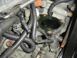
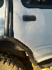
1. How it looked when I brought it home.
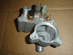
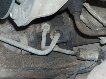
2.The M90 supercharger installed
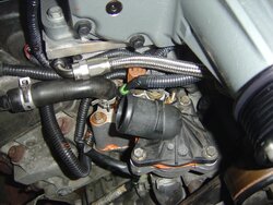
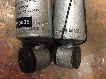
3.The GT500 supercharger installed
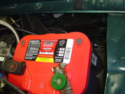
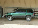
4.How it looks now
5.Wheelie
green ex.jpg
DSC02710.JPG
5.JPG
Lowered Rear.jpg
Exploder wheelie.jpg


Join the Elite Explorers for $20 each year.
Elite Explorer members see no advertisements, no banner ads, no double underlined links,.
Add an avatar, upload photo attachments, and more!
.


The number designates the cubic inch displacement of the blower: M90 = 1.475L, M112 = 1.835L, M122 = 1.999L as John posted.

Excellent Dale, that makes more sense. I can do the near 60 cubic inches per liter math.:thumbsup:


Join the Elite Explorers for $20 each year.
Elite Explorer members see no advertisements, no banner ads, no double underlined links,.
Add an avatar, upload photo attachments, and more!
.


Gauge Pod for Steering Column

I went to the junkyard yesterday and got a steering column cover to experiment with. Wanted to put a gauge pod on it.
 

Attachments

  • 6.JPG
    6.JPG
    126.5 KB · Views: 279
  • 5.JPG
    5.JPG
    122.4 KB · Views: 277
  • 4.JPG
    4.JPG
    130.2 KB · Views: 263
  • 3.JPG
    3.JPG
    144.2 KB · Views: 281
  • 2.JPG
    2.JPG
    126.5 KB · Views: 267
  • 1.JPG
    1.JPG
    117.7 KB · Views: 261


Gauge Pod

Installed.
Steering Column Pod # is 15004
 

Attachments

  • 8.JPG
    8.JPG
    118.6 KB · Views: 275
  • 7.JPG
    7.JPG
    125.4 KB · Views: 271


Where did the lower pillar mount come from? It sits low enough that it might not be very noticeable. I'm trying to keep my truck looking as stock as possible.

Very nice!


Ditto, very nice. That's very close to what I had in mind. I'm not sure where I'd rather place the boost versus A/F gauges, which one on the pillar and which one on the column.

Has anyone seen a very small fuel pressure gauge, one that might go like that one there low on the pillar? I need a trans temp gauge more than the fuel pressure, but I'd still like one someplace.


Lower pillar mount

Dono,
The lower pillar mount is right off the pep boys shelf.
It is a universal single gauge pod made by Autometer.
Part number is 15204. it is a standard 2 1/16 size.
It doesn't fit well the way that is was intended to be installed, neither did the universal dual pillar mount so I ordered the dual pod mount for a ranger and that is the dual one you see in the picture. I then tried the universal single pod and mounted it as seen. If you walk up on the drivers side from the back you would never know it is there(stealth). If you look through the windshield at the sticker you can see it but not the gauge face so you would not know what it was. I do have to remove it when the sticker is being replaced every two years since it is in the way of the sticker.


pod

cdw6212r,
That lower pod is same size as the other two. 2 1/16.
It just looks smaller in the picture because it is farther away.

The next gauge up from the lower pod is a fuel pressure gauge 2 1/16.
It would fit right in there. The gauge is a rebadged Autometer one for Roush.

I know what you mean about trying to decide what gauge to put where. I may change it later. I am trying to get rid of the pillar pods to be more sleeperish.
I figure that wideband is the most important to me at WOT, but it used to be where the lower pod is and that worked just fine. Where it is now it might light up my face at night.


Thanks, I can work with that 2.063 size being there, it looks great. Mine are all blue digital, and I hope they aren't going to be too bright.

We are blessed with one of the biggest instrument clusters and layout. I've wondered in conversation to one of the gauge makers, techs, about burying gauges in the dash, and feeding the output wires to LED displays, show through tiny holes in the cluster. I'd love to have readings of actual oil pressure, coolant temp, voltage, and maybe the fuel pressure with the level.

If you might need more stealth, the left air vent could be used to locate one of those multiple display gauges. I doubt that those display all of these needed items though. They like to include tach, speed etc, stuff we don't need or already have.


T Stat Housing

On the 4.0 sohc Ford used a plastic thermostat housing. Over time they start leaking. A very clever person has made aluminum replacements.
http://www.explorerforum.com/forums/showthread.php?t=362922
I was lucky enough to get one a while back and finally got around to installing it. I took this opportunity to add a few extra sensors, one is for the SPAL electric fan controller and the other is for an Autometer coolant temp gauge.
 

Attachments

  • 1.JPG
    1.JPG
    159.8 KB · Views: 240
  • 2.JPG
    2.JPG
    135.6 KB · Views: 241
  • 3.JPG
    3.JPG
    144.9 KB · Views: 253


optimum electric fan sensor location

After giving the electric cooling fan sensor location some consideration I think it should be in the water pump/radiator external cooling loop. If it is located in the internal loop (lower thermostat housing) the thermostat will maintain the coolant temperature in the block at the proper setting and the only time the cooling fan sensor will be deactivated is during engine warm up. If located in the external cooling loop it can be activated to keep the radiator temperature cool so when the thermostat opens additional cooling will be available. Past measurements with my remote reading thermometer indicate that the highest radiator temperature is near the top (heat rises). However, I think the water pump pulls water from the radiator bottom port so that may be the optimum location for the sensor.


fan switch

I think most American made vehicles had the Fan switch in what you call the internal loop. Their fans did not run continuous and neither has mine.
The thermostat will open and close to maintain the engine at the rating of the thermostat. If the engine temps go higher then somewhere it will turn on the fan.
I did an experiment years ago when single speed electric fans first came out.
The fan would turn on at these temps.
GM 235
Dodge 236
Ford 242
Any where over those temps were overheating. These were vehicles with 185 degree thermostats too.
Also Keep in mind these were older vehicles that did not have variable speed fans.
I did have a fan controller that had a temperature probe that was to be stuck in the radiator. I used it for a while and it worked so the sensor can be placed on either side of the coolant system.


OEM rationale

So I guess the OEM rationale is to wait until the radiator coolant is too warm to decrease the internal coolant temperature to the thermostat setting. I guess that reduces the fan run time. My rationale was to turn on the fan when the radiator coolant temperature exceeded the value needed to maintain the thermostat setting when the thermostat was open. I think that approach would be more appropriate for drag racing but less appropriate for daily driving. During normal NA driving my ECT rarely exceeded the thermostat setting by more than a degree according to my data logs. However, during my NA dyno testing the ECT increased to 214 degrees during one of the NA pulls. Recently, during short FI pulls around town I've logged ECTs as high as 204 degrees. My Volvo 850 Turbo wagon has a two speed electric cooling fan. I'll have to see if I can determine where the sensor is located.


SPAL fan controller

The SPAL PWM fan controller looks like a versatile unit. I didn't see the operating temperature limits for the controller or the max current capability. However, the suggested fuse maximum is 30 amps so the controller probably has a capability of 25 amps or so. The instructions mention it can be mounted in the engine compartment so the operating temperature must be at least 150 degrees F. but should be higher. Is your unit mounted in the engine bay? Have you experienced any controller overheating issues? I don't have much room for an electric cooling fan with the 2 inch thick radiator core. What electric cooling fan are you using? Is the cooling adequate?


Spal

Page 1 post #9 of this thread has the cooling fan on it, and the first fan controller is in post 10.

I will look for a picture of the Spal controller to post since it is not in any already.


Spal Fan Controller

Spal
 

Attachments

  • DSC06959.JPG
    DSC06959.JPG
    148.5 KB · Views: 211


M122 on a 2nd Gen Explorer

M122 + 2nd Gen Explorer.........


we know a m112 will clear the hood :D
i dont even have it on yet, and [MENTION=119708]ahodges[/MENTION] and i are trying to see if a m122 will fit lol


DSC00108.JPG
M122 Intercooled

Here it comes...


Join the Elite Explorers for $20 each year.
Elite Explorer members see no advertisements, no banner ads, no double underlined links,.
Add an avatar, upload photo attachments, and more!
.


how much farther will it have to go back? looks like the snout pulley is forward of the rest of the pulleys in that pic


Back
Top