DOHC 4.6L V8 build | Ford Explorer Forums - Serious Explorations

  • Register Today It's free!

DOHC 4.6L V8 build

2000StreetRod

Moderator Emeritus
Joined
May 26, 2009
Messages
10,597
Reaction score
334
City, State
Greenville, SC
Year, Model & Trim Level
00 Sport FI, 03 Ltd V8
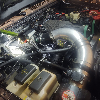
I bought a 2003 Aviator long block to install into a 2002 or 2003 Explorer that I hope to purchase in the future. See related thread: Next project vehicle? The Aviator was brought in to a tune-up shop because of a bottom end knock and the engine was swapped out to fix the knock. The mechanic who performed the swap is no longer employed at the shop so I have no details.

The engine is a modular Ford 4.6L DOHC V8 with four valves per cylinder.
FrontTrailer.jpg

LeftTrailer.jpg

The heads and block are identical to those used in the 2003 Mach 1. The stock Aviator intake system uses a single plate throttle body.
Aviator2.jpg

Since I have to purchase an intake system I decided to get one for a Mach 1 because it has a dual throttle plate oval intake.
Mach1b.jpg

I may use the included 24 lb/hr injectors which will require a custom tune since the stock Explorer PCM expects 19 lb/hr injectors. I intentionally purchased the Mach 1 intake system without fuel rails because they differ from the Aviator rails which has the fuel feed on the driver side and a pressure damper for each bank.
FuelRailTop.jpg


Join the Elite Explorers for $20 each year.
Elite Explorer members see no advertisements, no banner ads, no double underlined links,.
Add an avatar, upload photo attachments, and more!
.


Valve covers

I picked up a pair of Aviator valve covers at the local salvage yard.
ValveCoversTop.jpg

The middle section is removable to access the spark plugs located in a deep well in the heads.
ValveCoversBottom.jpg

This engine has coil over plug (COP) ignition unlike the 2nd generation with waste spark ignition. I purchased a set of used Mark VIII COPs and boots.
COPs.jpg

And a package of fasteners for the valve covers and the oil pan.


Exhaust manifolds

The Mach 1 exhaust manifolds are not impressive.
03Mach1.jpg

So I purchased a pair of Aviator exhaust manifolds from the local salvage yard.
ExhaustManifoldsa.jpg

ExhaustManifoldsb.jpg


All but four of the exhaust studs were missing from the heads and one of those was broken so I purchased a new set for each side (not stainless steel) and removed the existing studs.


Harmonic balancer

According to the eBay Mark VIII parts seller there are three different weights of harmonic balancers available. The heaviest one is recommended for engines in vehicles with an automatic transmission so that's what I purchased.
Balancer.jpg


Windage tray

My engine did not have a windage tray to prevent hp loss from oil splashing against the rotating crankshaft. I determined after some internet research that the Aviator was not produced with one but the Mach 1 had them fitted. Curiously, the 2004 Aviator workshop manual shows a windage tray in the engine disassembly instructions but none in the assembly instructions. I couldn't find a part number for a windage tray in Ford's database for either an Aviator or a Mach 1.
WindageTray1.jpg

WindageTray2.jpg

A windage tray can increase power by five to ten bhp at max engine speed. The problem with installing one is that the main bearing cap bolts that retain the tray must be replaced. There are aftermarket windage trays available but I've read they may need to be modified for the Mach 1. The Ford Mach 1 windage trays are getting scarce so I purchased one since there's a good chance I'll be pulling the main bearing caps to inspect the bearings.


Timing chain components

The timing chains and sprockets appear to be in good condition.
TimingChains.jpg

The guide surfaces that contact the chains are hardly worn and the cast (instead of molded?) tensioners seem to be functional. At this point I intend to reuse the timing chain components. Especially since they can be replaced with the engine in the vehicle at a later time.


Spark plugs

I removed all eight spark plugs with no problems. There were no indications of stripped threads in the heads. The 2003 heads only have four threads holding the plugs which are easily stripped if the plugs are over tightened when installed. The 2005 heads increased the number of threads from four to nine. All of the plugs showed normal wear (maybe 10K miles or more) with no signs of detonation.
SparkPlugs.jpg

Except for the plug from cylinder 6 with possible signs of fouling, there were no noticeable indications of anything abnormal.


Cool engine!

Is that going in another Sport?


Not seized

The shop manuals arrived today. I temporarily installed the crankshaft balancer and squirted engine oil down the spark plug holes to lubricate the cylinder walls and piston rings. I also oiled the camshaft lobes, valve springs, cam followers and lash adjusters. With my torque wrench set to 50 lb-ft I was able to rotate the crankshaft about 180 degrees before exceeding the setting. I think cylinder 8 intake valves were starting to open. I need to improvise a way to rotate the crankshaft counter-clockwise and to oil the bearings. At least the engine isn't seized after sitting for six months in the tune-up shop.


Something binding?

After rotating the engine on the stand to a position with the oil filter adapter ports up I poured oil into the gallery input port.
BlockLeftSide.jpg

Then I squirted oil on the bottom end. Repeatedly rotating the crankshaft clockwise and then counter-clockwise I was able to increase the rotation to about 300 degrees. But there is something binding when pistons 2 (on exhaust) and 8 (on compression) are near TDC.


Could be a bent rod causing the piston skirt to hit the counter weight on the crank.


bent rod?

Thanks, I'll check for that tomorrow. I didn't see any valves stuck open but I haven't checked thoroughly. I'll also look thru the intake and exhaust ports at the valves for foreign objects. Anything could have fallen into the intake ports after sitting uncovered for six months. According to the shop manual three special tools are needed to remove the heads and I don't have any of them. There's a tool to compress the intake valve springs (303-452/T93P-6565-AR)and another to compress the exhaust valve springs (303-567/T97P-6565-AH). There's also a special tool to protect the valve stem seals when compressing the springs (303-382/T91P-6565-AH). I think the compressor tools cost about $100 each used. I'll think about improvising an alternative.

Edit: I found a tool on the internet for $160 that's supposed to work on my 4.0L SOHC V6 and modular 2 valve and 4 valve V8s.
ST-103.jpg

It's made in the USA from pre-heat treated and annealed 4140 steel by Automotive Specialty Tools. It has a lifetime manufacturer's warranty and I purchased it thru Amazon who is pretty good about refunds for returned defective items. Another listing shows three spring adapters instead of two.
ST-103a.jpg


Very interesting.... Subscribing :)


Great thread. Subscribed.

Had a couple cars with that 32 valve V8 and found it an extremely effective engine. It is a very tall engine compared to the land of 302's.

Didn't know you were a Volvo nut also.


Join the Elite Explorers for $20 each year.
Elite Explorer members see no advertisements, no banner ads, no double underlined links,.
Add an avatar, upload photo attachments, and more!
.


Stuck valves?

I did not find any interference between the piston skirts and the counter weights although they get very close. The small end of the rods are all centered on the piston pins and no rods look bent.

I'm beginning to think there are stuck valves - valve stems rusted to valve guides. With the engine in its current position on the stand I was able to oil all of the intake valve stems and one bank of exhaust valve stems. As I rotated the crankshaft clockwise and counter-clockwise I could "popping" in the head area which I suspect was sticking valves releasing. I couldn't apply much force counter-clockwise because the balancer retainer bolt would just loosen. I found three bolts the same thread as the crankshaft and long enough to pry against but short enough to clear the stand when fully installed. I cut three lengths of hose to cover the exposed bolt threads. Now I can apply more force counter-clockwise using a pry bar against the crankshaft bolts.

Tomorrow I'll rotate the engine on the stand to a position for oiling the other bank of exhaust valves. If that doesn't help I'll wait until the valve spring compressor tool arrives. Then I'll remove all of the cam followers and try again rotating the crankshaft.


Back
Top