JTX's Return! 1997 Mountaineer Build Thread SAS/4wd Conversion | Ford Explorer Forums - Serious Explorations

  • Register Today It's free!

JTX's Return! 1997 Mountaineer Build Thread SAS/4wd Conversion

I've been gone for several years after losing the transmission in my 94 Ford Explorer(almost 10 years ago!:eek:). Life has changed a lot since then, I got Married, had a Child, and am having another one any day. Some of my greatest memories growing up came from my 1994 Ford Explorer. Memories with my Father, Friends, and several life lessons through High School.

Once my Son Luke was born I realized I would love to carry on these same memories with him and my Dad. I originally planned on redoing my 1994 Ford Explorer, but after looking at it and realizing some of the hack jobs I did to it in High School I decided to start fresh.

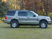
My second vehicle was a 97 Mercury Mountaineer. I decided to use this vehicle for several reasons. I liked the V8 and figured the interior would be better for four wheeling with my family. After I had the Mountaineer it was passed on to my Sister and drove until 2010. After that it sat for about 2 years until I started this project. Here is a list of the problems it had when I started.

  • Blown Head Gasket
  • 200k Miles
  • Front Suspension was Shot
  • Was no longer running

The first thing I did was pick up a new Motor and Transmission from the local U Pull. The engine and AWD transmission came from a 98 Explorer with 90k miles.

DSC_0267_zpsc1d23e9a.jpg

Taking the old Motor out. Son and Grandfather.

When I picked up the engine I also pulled a 4406 Transfer Case. The Mountaineer started as 2wd, so this will be a 4wd Conversion as well.

At this point the Mountaineer sat for about 6 months. Once I finally got the new Motor and Transmission in I decided to start the SAS. I probably should have got it running first but I needed a little motivation to get things rolling.

IMAG0507_zps4bc06e1c.jpg

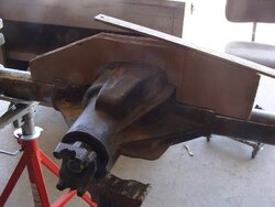
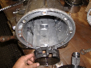
Ford 9inch from 94 Explorer. 4.88 Gears and Full Spool.

IMAG0508_zpsebae6c3e.jpg


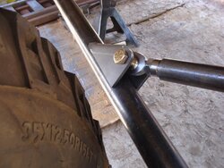
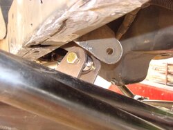
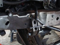
The SAS was done by Brian1 of the Forum. I wanted to make sure everything was done right this time around so I talked to Brian and we worked out a plan for the front end.
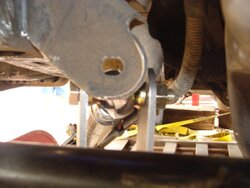
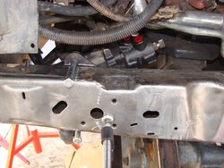
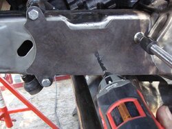
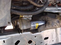
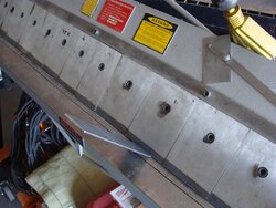
IMAG0570_zps19ed7bb4.jpg

IMAG0569_zpsc867df4d.jpg

Prepping the Frame

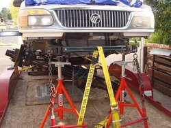
Once the Frame was prepped i was ready to take it to Brian.
10529702_10204229259555485_1455209045_n.jpg


Brian needed to be able to move the Mountaineer around so we decided to leave it on the trailer during the swap.


Join the Elite Explorers for $20 each year.
Elite Explorer members see no advertisements, no banner ads, no double underlined links,.
Add an avatar, upload photo attachments, and more!
.


Dana 44 work

While Joey was busy cleaning the frame of the IFS brackets and doing the rear axle swap he brought over the axle he was going to use so I could get a head start on it. It is out of a Ford F250 and is a high pinion Dana 44 that used leaf springs and not radius arms.

I started out by setting up his old 4.88 gears in this new housing. The gear install went pretty easy.

I then milled the flat top knuckle on the passenger side for the high steer arms. The driver side knuckle was already milled and tapped from the factory.

Next I cut into the housing to make room for the driver side link mount. The housing was big and beefy, all I did was cut it back some removing most of the built in leaf spring perch while retaining the ribbing. This was done with a porta-band and a chisel. Came off real easy and clean!
 

Attachments

  • m_DSC09567.jpg
    m_DSC09567.jpg
    76.4 KB · Views: 570
  • m_DSC09565.jpg
    m_DSC09565.jpg
    122.4 KB · Views: 572
  • m_DSC09564.jpg
    m_DSC09564.jpg
    99.9 KB · Views: 567
  • m_DSC09562.jpg
    m_DSC09562.jpg
    96.7 KB · Views: 581
  • m_Machining Knuckle.jpg
    m_Machining Knuckle.jpg
    86.6 KB · Views: 563


Dana 44 Truss

Once that was done the housing was ready for a truss. I did not like any of the aftermarket truss options out there. They either looked horrible, wasn't a true truss but more of a link tower, were too bulky or just not made for a Ford 44 at all.

I started by making a cardboard cutout of the shape of the diff using a contour gauge and a laser level that projected a line onto the full width of the axle. The truss would be made out of 2" x 6" x 1/4" rectangular tubing. I made it in 3 pieces to maximize the material and to make the fit a bit easier. The seams were welded up and then ground smooth for a seamless truss.

I then tack welded the entire truss to the axle and over the course of a day laid down some welds about 3" at a time alternating areas and allowing to cool before welding again to minimize any warping. To weld to the housing I heated the center up with a torch then welded using the same method as before but also adding in some post-heat and covering the diff with a heavy welding blanket to allow it to cool much slower.
 

Attachments

  • m_DSC09581.jpg
    m_DSC09581.jpg
    85.6 KB · Views: 572
  • m_DSC09580.jpg
    m_DSC09580.jpg
    74.1 KB · Views: 585
  • m_DSC09574.jpg
    m_DSC09574.jpg
    104 KB · Views: 558
  • m_DSC09573.jpg
    m_DSC09573.jpg
    88.3 KB · Views: 585
  • m_DSC09572.jpg
    m_DSC09572.jpg
    67.6 KB · Views: 597
  • m_DSC09571.jpg
    m_DSC09571.jpg
    81.9 KB · Views: 560


As Joey said above, all of the work will be done to the Mounty on the trailer AKA mobile work platform :D

Once he brought it over I got it raised back up and on jack stands. I made a temporary crossmember for the front of the frame out of some scrap metal and then started more cutting.

First to go was the transmission cross member. The plasma made quick work and then a 9" grinder ate up what was left. A little finishing work with the small 4.5 grinder and the frame was prepped for the new link brackets and new cross member.

I already had a set of my custom frame brackets made up, I run these exact same brackets on my own Explorer with extended arms and TTB. There are also 2 other sets out there in use. I positioned them in place to line up with the transmission mount making sure they were both square and in the same position on the frame. Once I was satisfied with the placement i then clamped them in place and used a transfer punch to mark the holes on the frame. I used a step bit to drill the holes with a close quarters drill. 3, 1/2" bolts through the side and 1, 1/2" bolt through the bottom not visible in the picture for a total of 4 bolts holding each side to the frame.

I machined some solid steel "bushings" that will be the attachment for the transmission cross member later on. They fit between the tabs on the frame brackets.
 

Attachments

  • m_DSC09604.jpg
    m_DSC09604.jpg
    104.1 KB · Views: 553
  • m_DSC09616.jpg
    m_DSC09616.jpg
    63.8 KB · Views: 547
  • m_DSC09615.jpg
    m_DSC09615.jpg
    102.5 KB · Views: 614
  • m_DSC09614.jpg
    m_DSC09614.jpg
    89.5 KB · Views: 548
  • m_DSC09609.jpg
    m_DSC09609.jpg
    105.8 KB · Views: 537
  • m_DSC09613.jpg
    m_DSC09613.jpg
    110.6 KB · Views: 557


Next it was time to put the axle under it for the first time to start getting an idea of links, steering, wheelbase, etc. but first the front cross member had to go. Out came the plasma again and then the grinder. JTX came over a couple of times to help out with grinding duties which allowed me to focus on other aspects of the project.

I also took a wire wheel to the frame to polish it up and get it ready for plating.

We got the axle under it and positioned about where it needed to be. We were able to reuse the HD steering I had made for his old Explorer many years ago and installed it on the high steer arms.
 

Attachments

  • m_DSC09624.jpg
    m_DSC09624.jpg
    125.6 KB · Views: 556
  • m_DSC09621.jpg
    m_DSC09621.jpg
    119.7 KB · Views: 559
  • m_DSC09620.jpg
    m_DSC09620.jpg
    91.6 KB · Views: 582


Frame Plates and Lower Axle Link Bracket

While the axle was mocked up under there I took a ton of measurements and then opened up Solidworks and started drawing. At this point we also decided to use a 1st gen steering box from his old Explorer so I also made a mounting plate for it.

The frame plates and inside steering box mount are made out of 3/16" plate to add strength to the frame and be the base of the shock mounts, steering box bolts and other things to come... I can easily reproduce these plates as well.

The lower axle link brackets are made out of 1/4" plate and the lower plate will partially wrap under the axle tube for extra strength. They are cut for a slight ~5 degree angle to the axle tube for the links to fit properly.

While the 1/4" was on my plasma table I went ahead and cut some extra parts I will need later on in the build like the axle coilover mount tabs and some tube flanges. I also cut the transmission mounting plate out of some 1/8" to get a start on it.

I tacked the lower link mounts together to get a start on mocking up the suspension.

Lastly, a friend of mine had a Bronco he parted out and he gave me the pitman arm off of it. It is almost a straight arm and should be just about right for the steering geometry. You can see the Ford part number on it.
 

Attachments

  • m_DSC09628.jpg
    m_DSC09628.jpg
    130.8 KB · Views: 549
  • m_DSC09633.jpg
    m_DSC09633.jpg
    109 KB · Views: 541
  • m_DSC09634.jpg
    m_DSC09634.jpg
    84.8 KB · Views: 570
  • m_DSC09632.jpg
    m_DSC09632.jpg
    107.1 KB · Views: 577
  • m_DSC09626.jpg
    m_DSC09626.jpg
    120.4 KB · Views: 574
  • m_DSC09631.jpg
    m_DSC09631.jpg
    107.1 KB · Views: 586


Lower Link Mockup

Moving day! The downside of having it on a trailer was the fenders being in the way. It was loaded a little too far forward and I couldn't fit the 35" tires on it to check for clearances. I picked up the entire front of the Merc with the gantry and moved it about a foot towards the back of the trailer.

I was then able to get the tires on it and turned to full lock to check the tire to link clearance. I cut the lowers to length setting the wheelbase 2" forward of stock at 113.5" Lowers are 2" x .25 wall DOM. I notched them for the bushing end at the axle and also drilled them for plug welds on the mill. The frame end uses 1.25" heim joints from Ruffstuff.
 

Attachments

  • m_DSC09637.jpg
    m_DSC09637.jpg
    115.9 KB · Views: 552
  • m_DSC09638.jpg
    m_DSC09638.jpg
    101.3 KB · Views: 549
  • m_DSC09650.jpg
    m_DSC09650.jpg
    93.7 KB · Views: 558
  • m_DSC09645.jpg
    m_DSC09645.jpg
    98.7 KB · Views: 556


Keep up the awesome work guys. Wish I had someone to help me with my SAS, doing everything myself. I'll be watching this build closely.

:popcorn:


Mocking up the Upper Links

I mocked up the upper links using 1.5 x .25" DOM to see where they needed to go and the length as well as draw up the brackets to weld to the truss and get ready to weld them on. We did use a pre-made bracket from Ruffstuff to attach the uppers to the lower link to slightly speed up the process. This would be the only store bough bracket we will be using. Links will be at 8" vertical separation and the upper width will be very close to a Jeep TJ front axle.
 

Attachments

  • m_DSC09651.jpg
    m_DSC09651.jpg
    108.2 KB · Views: 524
  • m_DSC09653.jpg
    m_DSC09653.jpg
    86.4 KB · Views: 547
  • m_DSC09652.jpg
    m_DSC09652.jpg
    108.2 KB · Views: 534


More Grinding + Reaming the TRE and Pitman Arm + Steering Box Mount

Joey came back over again to do some more grinding on the brackets I cut off earlier. We took the axle out to give more room for grinding the frame and I would be welding the upper link tabs on it later off the trailer. While he was grinding the frame I reamed out the tie rod end and the pitman arm with the GM taper.

His old steering went under the knuckle arm and this time we flipped it to the top of the high steer arm. While we were able to reuse most of the steering from his old Explorer as I mentioned above, the tie rod end with the hole for the drag link was reamed the opposite way since we flipped it. We got another one and I reamed it the correct direction for being mounted on top of the arm/knuckle.

I also worked on the inside steering box mount welding on the spacers I machined to space the box out from the plate to mount it flat.
 

Attachments

  • m_DSC09658.jpg
    m_DSC09658.jpg
    98.7 KB · Views: 527
  • m_DSC09659.jpg
    m_DSC09659.jpg
    113.6 KB · Views: 525
  • m_DSC09660.jpg
    m_DSC09660.jpg
    95.6 KB · Views: 542
  • m_DSC09663.jpg
    m_DSC09663.jpg
    84.1 KB · Views: 535


Nice work! It's great to hear that you are going to be back on the trail Joey :chug:


Upper Links Installed

After some careful measuring of lengths and angles I tack welded the upper link tabs to the axle truss with the axle out of the Mounty. The links were also drilled for plug welds and the bungs tack welded to the links. Then I put the axle back under and hooked up the lower links to the frame and couldn't resist a test flex. The lower tabs of the motor mounts will definitely have to be trimmed!

You may also notice the chains and ratchet boomers on the front of the frame. One benefit to working on a trailer is that it acts as a big chassis "table" and I was able to crank down on the frame to keep it straight through the process of cutting off the stock cross members and then adding new ones.
 

Attachments

  • m_DSC09675.jpg
    m_DSC09675.jpg
    137.8 KB · Views: 521
  • m_DSC09671.jpg
    m_DSC09671.jpg
    118.8 KB · Views: 529
  • m_DSC09677.jpg
    m_DSC09677.jpg
    77.3 KB · Views: 527
  • m_DSC09665.jpg
    m_DSC09665.jpg
    119.5 KB · Views: 516
  • m_DSC09680.jpg
    m_DSC09680.jpg
    63.4 KB · Views: 547
  • m_DSC09676.jpg
    m_DSC09676.jpg
    115.3 KB · Views: 523


Steering Box

Now with the axle in place front to back I could work on positioning the steering box. Joey had already installed a remote mount oil filter when he dropped in his new engine making room for the inside frame steering box.

The spread of the bolts were enough to fit over the frame but just barely. They were a little too tight for my liking so I machined some sleeves for the bolts that would be sunk into the frame. I notched the top and bottom of the frame and then welded in the spacers. I tack welded the inside plate in a couple spots to the frame as well.

Once the box was in its place I measured where the bolt holes were and then modified my frame plate CAD file to include the 3 bolt holes for the driver side of the frame. I left the 3rd hole that passes through the frame as a pilot hole to make it easier to drill through the frame. I cut it out on my plasma table and then bolted it up to the frame/steering box and then drilled the 3rd hole.
 

Attachments

  • m_DSC09684.jpg
    m_DSC09684.jpg
    104.7 KB · Views: 528
  • m_DSC09687.jpg
    m_DSC09687.jpg
    90.9 KB · Views: 515
  • m_DSC09691.jpg
    m_DSC09691.jpg
    94.7 KB · Views: 536
  • m_DSC09689.jpg
    m_DSC09689.jpg
    90.2 KB · Views: 520
  • m_DSC09690.jpg
    m_DSC09690.jpg
    100.3 KB · Views: 527


Transmission Crossmember Pt 1

Once the box was mounted I turned my attention back to making the rest of the transmission crossmember. This would be similar to what I have been running on my Explorer for years but modified to fit the 2nd generation Explorer/Mountaineer

I had cut the mount plate earlier so measuring off that and between the solid bushings I drew up the crossmember then cut it out of 1/8" sheet on my plasma table. I dimpled the holes in the middle for strength and then set them in place and tack welded the 2 sides to the top plate.

I guesstimated the clearance need for driveshaft droop with a spare shaft I had laying around. Also, the stock exhaust was long gone and would be replaced with a custom one later in the project so I didn't have to worry too much about clearing the stock exhaust. Still plenty of room left to run some pipes through the passenger side of the t-case.
 

Attachments

  • m_DSC09693.jpg
    m_DSC09693.jpg
    143.1 KB · Views: 487
  • m_DSC09692.jpg
    m_DSC09692.jpg
    101.2 KB · Views: 506
  • m_DSC09698.jpg
    m_DSC09698.jpg
    111.4 KB · Views: 516
  • m_DSC09702.jpg
    m_DSC09702.jpg
    89.4 KB · Views: 483
  • m_DSC09695.jpg
    m_DSC09695.jpg
    117.6 KB · Views: 488


Transmission Crossmember Pt 2 + Rear Shackles

With the 2 sides tack welded together of the crossmember I could now box it in with some 2" x 1/8" strap. I bent the pieces on my box and pan brake and then got those tacked welded. Once the crossmember was ready to be fully welded I built a fixture out of some scrap metal so it wouldn't warp during welding.

I got it painted and then installed. The transmission mount bolts can easily be accessed through the bottom of the crossmember.

I also cut some new shackles for the rear because his factory ones were almost maxed out on the frame and I also needed to bring it up slightly so the rear ride height will match the front ride height. I have built several sets of shackles so to make it go faster I made those red spacers a few years ago. They are a little oversized on width. After welding, the spacers are removed and then the shackle closes up slightly making them the perfect fir over the bushings.
 

Attachments

  • m_DSC09712.jpg
    m_DSC09712.jpg
    139.9 KB · Views: 517
  • m_DSC09710.jpg
    m_DSC09710.jpg
    113.1 KB · Views: 485
  • m_DSC09708.jpg
    m_DSC09708.jpg
    95.7 KB · Views: 502
  • m_DSC09707.jpg
    m_DSC09707.jpg
    105 KB · Views: 493
  • m_DSC09704.jpg
    m_DSC09704.jpg
    95.9 KB · Views: 473
  • m_DSC09741.jpg
    m_DSC09741.jpg
    97.6 KB · Views: 516


Trackbar Frame Side

Next up came the trackbar. What a pain this was going to be threading the needle. The high steer arms are a bit shorter in length so on full lock the tie rod gets close to the truss and diff cover. The track bar is going to be 1.5" x .25" DOM tube.

I had 2 goals for the trackbar. 1 - keep it straight with no bends for strength and 2 - (the most common one) be the same length and angle as the drag link.

I set the suspension at full bump which is where I like to build my suspensions, it lets you maximize your uptravel and see where things are going to hit and you can build accordingly. I also would set the axle at ride height a few times to check the angles of the trackbar and the drag link.

The frame plate on the driver side was going to be the base of my trackbar mount. I took a few measurements then drew up a design in Solidworks. Once I was satisfied it would work I cut the pieces out of 1/4" steel. The strip between the plates was bent on my home made press brake.

I got it mocked up and tack welded to the frame plate. Since the trackbar doesn't need much misalignment I used safety washers to provide enough room for the heims to move around while keeping the bracket narrow. I did try mocking it up with the high misalignment inserts at first but quickly found it would be too wide and hit everything :banghead:
 

Attachments

  • m_DSC09738.jpg
    m_DSC09738.jpg
    73.6 KB · Views: 491
  • m_trackbar frame bracket assembly.jpg
    m_trackbar frame bracket assembly.jpg
    18 KB · Views: 490
  • m_DSC09713.jpg
    m_DSC09713.jpg
    100.7 KB · Views: 512
  • m_DSC09714.jpg
    m_DSC09714.jpg
    60.4 KB · Views: 481


Trackbar Axle Side

With the frame mount set I cut the tube to length for the trackbar making it about 32" eye to eye which is the same as the drag link. From there I could figure out the axle side and the height it needed to be off the truss to get it to the same angle as the drag link.

Back to Solidworks again to draw up the axle bracket. The front side would be bent to angle back towards the axle tube and the back plate would sit on top of the truss. The strip between the plates would also be bent and when I drew it up, I left it a little oversize for a custom fit. I laid it against the 2 plates and drew where I needed to notch away the material. I took it over to my hydraulic Ironworker where 50 tons of force notches 1/4" steel like butter :D

Clearences were tight all the way around but I managed to keep the bar straight. The trackbar was very close to hitting the oil pan on full stuff. To make it not hit, the angles of the trackbar and drag link are slightly off but should be close enough to not notice any bumpsteer.

The heims use a 3/4" Grade 8 bolt at each attachment point. The bolt heads were massive so I had to trim them down a little bit on the lathe so when the wheel was turned to full lock the tie rod would not rub on the bolt.
 

Attachments

  • m_DSC09735.jpg
    m_DSC09735.jpg
    79.1 KB · Views: 465
  • m_DSC09734.jpg
    m_DSC09734.jpg
    72.6 KB · Views: 488
  • m_DSC09731.jpg
    m_DSC09731.jpg
    53.1 KB · Views: 476
  • m_DSC09725.jpg
    m_DSC09725.jpg
    94.1 KB · Views: 473
  • m_DSC09742.jpg
    m_DSC09742.jpg
    102.9 KB · Views: 468


Beautiful work Brian. 1st class :D


Join the Elite Explorers for $20 each year.
Elite Explorer members see no advertisements, no banner ads, no double underlined links,.
Add an avatar, upload photo attachments, and more!
.


Back
Top