Screenshot of relevant portion of attached PDF
Something screwy happened with my prior post, I "thought" I had edited it to replace the video link (which after I watched it further, the guy never even revealed if what he showed, worked, like he didn't know if it would. He did have the right idea though, I just don't know if the pins he picked were correct.
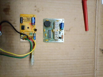
I had replaced that video link with suggestions to use a multimeter to check low resistance/continuity between the sending unit wire and which dash cluster connector pin that corresponds to, then once that is found, which slosh module pin has continuity to that cluster contact. This gives the input signal contact, then check the other slosh module contacts for continuity to one of the fuel gauge contacts, to determine which is the output pin, and then you can connect input pin to output pin on the slosh module with a jumper wire. Instead of tracing the first part with a multimeter you could also look at the wiring diagrams for the connector # and pin # on each, as shown in the pic below and the rest of the instrument cluster diagrams, but since the diagrams don't include a pinout for the slosh module itself, continuity between each of its pins and the fuel gauge seems necessary, unless it can be reverse engineered from the circuit board itself.
In other words, suppose the PCB has an LM2902 quad (4 channel) opamp, then using the LM2902 datasheet, see which input on the IC that the sending unit is going to, then on the same opamp channel, which pin contact on the PCB that same channel's output is going to.
IIRC I'd also posted that I would prefer to instead (or at least as the first attempt related to the slosh module) try replacing the large electrolytic capacitor and retouching all suspect solder joints, particularly on the largest resistor just across from that capacitor.


