-
Performance Upgrades - Maintenance - Modifications - Problem Solving - Off-Road - Street Trucks.
Covering the Explorer, ST, Sport, Lincoln Aviator, Sport Trac,
Mercury Mountaineer, Mazda Navajo, Ford Ranger, Mazda Pickups, and the Aerostar.
Featuring H.I. - Human Intelligence.
Register Today It's free!
You are using an out of date browser. It may not display this or other websites correctly.
You should upgrade or use an alternative browser.
You should upgrade or use an alternative browser.
Radio LED display fix!!!
- Thread starter bseblfevr9
- Start date
Elite Explorer members see no advertisements, no banner ads, no double underlined links,.
Add an avatar, upload photo attachments, and more!.
golfnmore
New Member
- Joined
- July 27, 2005
- Messages
- 2
- Reaction score
- 0
- City, State
- Detroit, MI
- Year, Model & Trim Level
- '98 Eddie Bauer
Very nice info...for what it's worth, I've now fixed 6 radios for family and friends, starting with my own (both in Explorers and Nissan Quest mininvans - same radio). I used the Save My Sanity swap program at www.shareamemory.com/radio. It's cheaper than buying the board from Pioneer, and if the board is not your problem (I ran into this once), they will let you return the board for a complete refund (no hassle)! It's been great using the service and you don't have to ship your radio anywhere.
KC
Active Member
- Joined
- February 6, 2004
- Messages
- 55
- Reaction score
- 0
- City, State
- Pittsburg,CA
- Year, Model & Trim Level
- '01 EB SOHC
August, 2005 Over a year and my display is STILL Working!! WooHoo!!!
Try it folks (that is resoldering the chips on the board), it's not that hard and saves you enough for a couple tanks of gas!!
Try it folks (that is resoldering the chips on the board), it's not that hard and saves you enough for a couple tanks of gas!!
Ford Radio
New Member
- Joined
- December 1, 2005
- Messages
- 1
- Reaction score
- 0
- City, State
- Wisconsin
- Year, Model & Trim Level
- 98 and others
Ford Radio Display Fade Fix --NEW THEORY?
I tried the fixes listed earlier in these posts with some success, but the problem always came back. Then I realized one constant appeared every time I pulled out the radio:
One of the four joints holding the "heat shield" in place was always (re)cracked, despite my previous efforts to fix it, every time.
My theory: If one of these joints is cracked, and the radio heats up, the metal could easily pull away from the circuit board, thereby "breaking" any electrical connection. I suspect the heat shield is more than a heat shield and actually makes a required electrical connection.
THEREFORE: For those of you pulling your radio apart for the first time, simply check these four joints very carefully. For some reason the solder doesn't seem to want to afix itself to the shield--apply more solder if necessary (it was for me) and "wrap" the solder around the four shield tabs--this should maintain the connection. (DO make certain any extra solder doesn't contact any other components or part of the reassembled radio.)
If this doesn't fix the problem then proceed with checking the other components on the display board.
Regards & good luck.
gijoecam
Village Idiot
- Joined
- May 31, 1999
- Messages
- 8,336
- Reaction score
- 17
- City, State
- Trenton, MI
- Year, Model & Trim Level
- 98 ExSport, '00 F-150
Ford Radio said:I tried the fixes listed earlier in these posts with some success, but the problem always came back. Then I realized one constant appeared every time I pulled out the radio:
One of the four joints holding the "heat shield" in place was always (re)cracked, despite my previous efforts to fix it, every time.
My theory: If one of these joints is cracked, and the radio heats up, the metal could easily pull away from the circuit board, thereby "breaking" any electrical connection. I suspect the heat shield is more than a heat shield and actually makes a required electrical connection.
THEREFORE: For those of you pulling your radio apart for the first time, simply check these four joints very carefully. For some reason the solder doesn't seem to want to afix itself to the shield--apply more solder if necessary (it was for me) and "wrap" the solder around the four shield tabs--this should maintain the connection. (DO make certain any extra solder doesn't contact any other components or part of the reassembled radio.)
If this doesn't fix the problem then proceed with checking the other components on the display board.
Regards & good luck.
I just shot that theory out of the water.... I had my metal shield completely off and was poking and prodding the resistors with a screwdriver (first mistake).... The display was flickering between bright and 3/4 bright, and I got all excited, and touched one of the contacts with a screwdriver that was also touching the chassis.... it shorted, let out a lot of smoke, and now nothing comes up when I turn it on. I might've blown a resistor, or might've torched the power supply. I guess it's off to the local pick-and-pull.

-Joe
rscalzo
Active Member
- Joined
- July 24, 2004
- Messages
- 66
- Reaction score
- 1
- Location
- Epping, NH
- City, State
- Epping, NH
- Year, Model & Trim Level
- 2021 XLT
- Callsign
- N1RDS
Display Repairs
I sent my radio out to:
VCR Service Stop
781-337-6800
288 Washington St.
Weymouth, MA 02188
Total cost of repair was $110.00 including return shipping. Turn around was less than a week. It is still working fine over a year later. :exp:
I sent my radio out to:
VCR Service Stop
781-337-6800
288 Washington St.
Weymouth, MA 02188
Total cost of repair was $110.00 including return shipping. Turn around was less than a week. It is still working fine over a year later. :exp:
KC
Active Member
- Joined
- February 6, 2004
- Messages
- 55
- Reaction score
- 0
- City, State
- Pittsburg,CA
- Year, Model & Trim Level
- '01 EB SOHC
Once again people, the shield is just that... A shield. Nothing more, nothing less. Problably more an RF shield than a heat shield. Either way it has nothing to do with the circuitry that makes the display work! Re-solder the surface mount resistors - That's what'll fix it! If you are shy about soldering - and there's nothing wrong with that - you probably know someone who can do it for you for a lot less than the $100+ fees that I've seen.
gijoecam
Village Idiot
- Joined
- May 31, 1999
- Messages
- 8,336
- Reaction score
- 17
- City, State
- Trenton, MI
- Year, Model & Trim Level
- 98 ExSport, '00 F-150
I ended up sending mine out to Trevor Wilcox at Pacific Audio in Washington. Ordinarily it's $60, but he said he'd charge an extra $10 to fix the chip that got smoked, and cover the return shipping on the deal. Sounds GREAT to me! Should be back next week.
-Joe
-Joe
D Whiteley
New Member
- Joined
- January 31, 2007
- Messages
- 8
- Reaction score
- 0
- City, State
- Fulton, Kentucky
- Year, Model & Trim Level
- Stock 99 XLT 2wd
Went to your listed sight. Where do I find your instructions?
D Whiteley
New Member
- Joined
- January 31, 2007
- Messages
- 8
- Reaction score
- 0
- City, State
- Fulton, Kentucky
- Year, Model & Trim Level
- Stock 99 XLT 2wd
Went there, found nothing
Went to your sight, found nothing about display problem.
THIS APPLIES TO FORD 98 & UP FORD DISPLAY GOING DIM OR BEING COMPLETELY OUT.....
I HAVE INSTRUCTIONS FOR YOU
Very Simple FIX TO THE PROBLEM
www.caraudiolabs.net
email me for instructions at
caraudiolab@aol.com
While perusing the Explorer usenet group, I ran across a posting (an ad, really) that contained this URL:
http://ourworld.compuserve.com/homepages/stereorepair/ford.htm
Sounds like they recognize the problem and its usual (exclusive?) cause. Anyone tried these folks out? I figure I'll try to fix it once more and if that doesn't do the trick I'll send the unit to them. $80 is a lot cheaper than a refurbed unit for $175 or so, even when you count in shipping charges.
Went to your sight, found nothing about display problem.
KC
Active Member
- Joined
- February 6, 2004
- Messages
- 55
- Reaction score
- 0
- City, State
- Pittsburg,CA
- Year, Model & Trim Level
- '01 EB SOHC
D. Whitely, not sure if you're looking for instructions to do the repair or do the replacement, but go back to page 5 of this thread and you will find not only my instructions for the repair, but other instructions and some links to follow if you want to replace it. I had posted a link in one of my posts that is now dead. I did some looking and I did in fact copy it so I will paste it here. This is what started me off in the right direction for repairing it:
~ ~ ~ ~ ~ ~ ~ ~ ~ ~ ~ ~ ~ ~ ~ ~ ~ ~
Posted by Dan on May 27, 03 at 08:50:10:
In Reply to: Re: Ford Explorer, 2000, Radio Display posted by megober3521 on February 06, 03 at 14:21:29:
I took the power supply out and you can see on the bottom of the board that it has gotten very hot by the discoloration. I also noticed a break in the solder joint on C1083 and R1064. I resoldered the joint and now my display works again. Great information for the fix!
: I had the
: same problem in my 98 Explorer. The problem is with the display power
: supply board getting too hot and cracking the poorly solder joints.
: You have two options if it's not under warranty. One, you can try to
: re-solder the joints. Two, you can replace the board. I tried to
: re-solder the board with no luck. I had to replace the board. I will
: include information at the bottom of this posting on where to buy the
: board. It took me a long time to find someone who sold the parts.
: Here are the instructions to re-solder the board. They were posted in
: a Ford radio news group.
: To try to re-solder the board....
: MAKE SURE YOU HAVE A LOW WATT SOLDERING IRON AND SMALL SOLDER.
: ~~~
: Here's the directions that helped me...Good Luck:
: By opening up the radio you will find a narrow display power board
: With in the left side of the radio (faceplate toward you). This board
: has a metal cover soldered to it, with a toroid (wire wound doughnut)
: inside on one side, and a bank of surface mount resistors and
: capacitors
: on the bottom side. One end of the board (SCR heat sink) is screwed
: to
: the heat sink at the back of the radio, the board is secured with 2
: metal bend-tabs, and it has a white mini connector on the other end
: which connects to the faceplate. Remove the board from the radio.
: On the bottom of the board look for surface mount components
: R1057/C1071/R1058/C1083/R1064. The colder these resistor/capacitor
: chipsets get, the brighter the display. I left the car out in the +5
: f
: degree weather and the display worked until it warmed up a little.
: That
: is how I was able to track it down to these temperature sensitive
: parts. Freeze-it also helped after I narrowed it down to a few
: components.
: Here is the contact information for vendors who sell the replacement
: board.
: Me~Gober wrote:
: I have traveled this road. I have a 1998 Ford Explorer with a blank
: radio display cd\cassette\am\fm. I tried to re-solder the components
: on the display power supply as suggested on previous posting with no
: luck. I looked on ebay but didn't see anything worth buying. I again
: tried to re-solder the board...still no luck. So this is what I have
: learned. If you can't fix it with the re-solder posting, or don't
: want to try it, you will need to replace the display power supply.
: Most radio shops I called said they only do component level repairs
: starting at $100.00. Then I found a few shops that have the circuit
: boards for sell. The board comes in a 3 board set, a new power
: supply
: board and two new tuner type boards, sold as a "compound set". Here
: are the shops I found that have it.
: Speed-O-Tach, Inc. they sell the 3 boards for 73.95 + shipping (5.00
: ish)
: Auto Radio & Electronics PART NUMBER HWM0043
: Corporate Office
: 4090 Pike Lane
: Concord, CA 94520-1227
: Toll Free: 1-800-442-4491
: Tel: 925-691-4090
: Fax: 925-691-4101
: or
: speedometerservice.com 3 boards cost is 82.82 6.75 shipping
: Phone number
: 1-800-332-1827 Georgia Watts
: 1-800-241-2385 National Watts
: I found other sites but the price jumped to 215.00!
: The board is very easy to swap. Pull the radio out, take to 2 black
: screws off the side of the face plate (1 on each side. Face the back
: of the radio, now remove the screw in the top right corner. Pop the
: front and top cover off the radio. Unplug the blue cable that leads
: from the display to the display power supply. There are 2 tabs that
: hold the power supply in. One is next to where the blue cable plugs
: into the power supply. To find the other tab, look inside the half
: circle on the tin heat shield. The board is painted white where the
: tabs are. Now straighten the tabs with a screw driver. Pull straight
: up on the tin heat shield. Now you have it out swap it with the new
: one and put it all back together.
Now I have not contacted any of the businesses listed at the end or anything else other than to get the idea of re-soldering not only the chips listed, but every one I could access, as well as raising the two blue resistors. And once again, the "Shield" on that board has absolutely no function in the circuit other than to block RF signals coming from the wire-wound coil located inside of it!
I have no idea how old the contact info contained in there is (the original post dates back to '03) so I can't say thEy still work but the instructions are still the same and should fix your problem. I repaired mine 3 years ago now and have not had a single issue with it since!
D Whiteley
New Member
- Joined
- January 31, 2007
- Messages
- 8
- Reaction score
- 0
- City, State
- Fulton, Kentucky
- Year, Model & Trim Level
- Stock 99 XLT 2wd
Thanks KC. I beleive I'm going to replace with an aftermarket system. Figure if this problem exists so widely, whats next? Thanks.
- Joined
- June 17, 2004
- Messages
- 24,273
- Reaction score
- 4,745
- City, State
- Knoxville, TN
- Year, Model & Trim Level
- 98 Limited AWD 302
It's just a bad display board, it is in all Mach and Premier models of those years. There is an expert that I know of that uses a Mach unit as his in studio tuner, for his business. He and others know those Pioneer units very well, they have fixed anything, and waranteed them.
I love the big buttons, the excellent reception, plus they are far less likely to be stolen. Good luck,
I love the big buttons, the excellent reception, plus they are far less likely to be stolen. Good luck,
D Whiteley
New Member
- Joined
- January 31, 2007
- Messages
- 8
- Reaction score
- 0
- City, State
- Fulton, Kentucky
- Year, Model & Trim Level
- Stock 99 XLT 2wd
Fixed for now.
I tried several times to fix this problem myself. Figured I had the back ground with my experience as a tech. I finally decided to order a repaired board from http://www.shareamemory.com/radio. My repairs looked prettier than theres, but they must know the secret. It works so far so good. The wifes happy anyway and thats the point. Thank you all for your input and incite.
I tried several times to fix this problem myself. Figured I had the back ground with my experience as a tech. I finally decided to order a repaired board from http://www.shareamemory.com/radio. My repairs looked prettier than theres, but they must know the secret. It works so far so good. The wifes happy anyway and thats the point. Thank you all for your input and incite.
gto78
Well-Known Member
- Joined
- June 18, 2006
- Messages
- 123
- Reaction score
- 0
- City, State
- stuart, fl
- Year, Model & Trim Level
- 98 EB 2wd v-6
I have the mach stereo in my 98 eddie bauer and the display has been burned for years. I bought a slightly different model stereo a while back on eBay and it works the same except no RDS or Subwoofer. I was thinking about stealing the power supply board from IT and installing it on my older broken display Mach stereo. Has anyone done this, will it fry anything? If it all looks the same I'll do it- if it smokes then I guess I'll be buying a Pioneer double din nav stereo unit to shut her up for ruining the already working radio in her truck.
- Joined
- June 17, 2004
- Messages
- 24,273
- Reaction score
- 4,745
- City, State
- Knoxville, TN
- Year, Model & Trim Level
- 98 Limited AWD 302
The repair for the display used to be typically $60, the actual board I believe is only about $20-25. It would be wise to buy the replacement board, or pay to have it installed. Good luck,
BruceH
New Member
- Joined
- December 14, 2006
- Messages
- 4
- Reaction score
- 0
- City, State
- Winnipeg, Manitoba
- Year, Model & Trim Level
- 99 Sport
I have the Mach stereo in my 98 Eddie Bauer and the display has been burned for years. I bought a slightly different model stereo a while back on eBay and it works the same except no RDS or Subwoofer. I was thinking about stealing the power supply board from IT and installing it on my older broken display Mach stereo. Has anyone done this, will it fry anything? If it all looks the same I'll do it- if it smokes then I guess I'll be buying a Pioneer double din nav stereo unit to shut her up for ruining the already working radio in her truck.
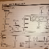
The power supply board should be the same between the radios. It should be easy to tell once they are side by side. The parts that cause the problems are the high wattage resistors:
R1060 - 3.3 ohm 2W
R1061 - 1.8 ohm 2W
R1062 - 2.2 ohm 2W
R1063 - 2.2 ohm 2W
A step by step fix was detailed by someone else and can be found at
http://www.mts.net/~joanlh/Radio_Display_Fix.pdf
The kit for repairing the radio is available from Pioneer as part number HWM0043. This consists of three circuit boards (EQ PCB, Connector PCB, VF SUB PCB - the failed unit). The VF SUB PCB consists of three "zones": 6.2V regulator, 27kHz Oscillator for VF filament (where the high wattage resistors are located) and a DC/DC Converter (-39V). The last time I priced this kit it was about $147, though this might have been the equivalent Canadian price. I believe it is closer to $100US.
96ExplorerLtd
Member
- Joined
- December 18, 2004
- Messages
- 10
- Reaction score
- 0
- City, State
- Lupton, Michigan
- Year, Model & Trim Level
- 2000 LTD V8
I just followed the directions and it works. Brushed it pretty well with a light brass brush, then followed that with a stiff nylon bristle and some air to clean it off. No liquids.
Ron Mellon
2000 LTD Now
Ron Mellon
2000 LTD Now
IAmTodd
4x Explorer Veteran
- Joined
- April 8, 2002
- Messages
- 8,851
- Reaction score
- 22
- City, State
- Johnstown, PA
- Year, Model & Trim Level
- 2015 Jeep
The Pioneer kit is $100-$110. I'm in contact now with a member on Ebay to see about fixing my newly aquired premium unit. It was mistreated by the previous owner and has some extensive damage. I'm waiting to hear back after sending pictures to this person. I may just end up buying the pioneer kit.
Elite Explorer members see no advertisements, no banner ads, no double underlined links,.
Add an avatar, upload photo attachments, and more!.
wrbrower
Member
- Joined
- January 14, 2004
- Messages
- 18
- Reaction score
- 0
- City, State
- Portland Oregon
- Year, Model & Trim Level
- 2001 EB 4x4
Pioneer link: http://parts.pioneerelectronics.com/part.asp?productNum=HWM0043
27,000 + views on this thread. Ya think this might be a problem???
27,000 + views on this thread. Ya think this might be a problem???
Based on a post by another person with a similar problem I contacted Pioneer who actually manufactured the radio that is in the Explorer's with the display problem. The parts number is (800)421-1404. Just follow the prompts until you get to the parts dept. The component you are looking for is called a Compound Unit. My radio's Ford Part number is YLZF-18C868-CA, in smaller print below you will see the Pioneer number, which is what you need. Mine is FH-2076ZF. At first they weren't sure what I needed, so I listed the part number that another poster had used and they where able to figure out what I needed. If asked, you should be able to tell them Compound unit for your model of radio and be good to go. The part number for mine is HWM0043. Evidently this is the 3rd substitute part for that radio which leads me to beleive its been improved upon a few times. Price of the part was about $88, worked out to $101.30 with two day shipping. I should have the parts on Friday and I will post my results then. If I have time I'll post some pictures of what I did and what the new vs old parts look like. Keeping in mind I've already resoldered them a few times.
Featured images


Featured images
Similar Threads
- Replies
- 8
- Views
- 1,439
- Replies
- 1
- Views
- 2,084
- Replies
- 0
- Views
- 2,607
- Replies
- 0
- Views
- 1,514
- Replies
- 2
- Views
- 1,758
- Replies
- 1
- Views
- 4,161