Tom Graham
Member
- Joined
- November 22, 2018
- Messages
- 20
- Reaction score
- 1
- Location
- Burns, Tennessee
- City, State
- Burns
- Year, Model & Trim Level
- 1995 Explorer XLT 4x4
ENGINE-OUT (removed from vehicle) PROCEDURES & STEPS FOR SYNCHRONIZER TIMING & CMP SENSOR BACK PROBE TEST ON 1995 4.0L OHV:
These are the steps (with improvised procedures) to precisely and correctly align your camshaft position sensor mounted on the synchronizer (with the sight glass) when the engine is out of the vehicle, on a 1995 Ford Explorer 4.0L OHV Pushrod V6 Engine with OBD1 DTC and EEC-IV PCM. First follow the steps to drop in your synchronizer then proceed with the following to perform the back probe test on the CMP (camshaft position) Sensor
1. First set the #1 Piston to TDC on Compression Stroke. The needle on the Crankshaft Pulley (Harmonic Balancer) points directly at 0 degree mark. Then loosen the synchronizer retaining bolt until the synchro body rotates easily.
2. Find the 26° mark ATDC (After Top Dead Center) on the Crankshaft Pulley. (No such mark was present on my pulley so I made a mark myself with a chisel & hammer with a light tap.
I first made the mark incorrectly then corrected after checking with tape measure. The mark should be 1 & 11/32" ATDC from the 0° mark (counterclockwise if facing the pulley.)
See image:

3. Using a torque wrench or breaker bar & 19mm Deep socket, turn the harmonic balancer clockwise two revolutions to take up any slack in the timing chain, stopping at the 0° mark.
4. Continue slowly turning the pulley clockwise until the pointer is on the 26° ATDC mark then stop.
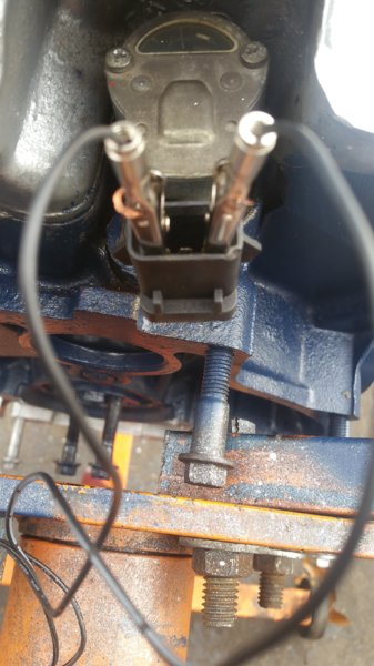
5. Note where the voltage indicator marks are for the 3 pins on the rear of the camshaft position sensor mounted on top of the synchronizer. One on the right is positive"+" middle is "0" and the left pin is negative "-" See image.

5. Using an AC to 12V DC Power transformer or a 12V DC Battery, (I used a 2 Amp 12V power supply for a WiFi router) connect the 12V Positive wire of the lead to the "+" pin on the CMP Sensor. Then connect the negative lead to the "-" pin. Then plug it in the wall or extension cord. Here is an image of the 2 Amp 12V DC power transformer I used for this test:

Here is an image of the power supply leads connected to the CMP Pins using alligator clips: (Make sure you have the 12V positive wire clipped onto the + pin on the CMP.
6. Set your volt meter to DC Volts to perform this test. Connect the negative probe to the negative aligator clip as shown in the image below.

7. Place the red or positive lead of the volt meter on the center CMP Sensor pin marked "0". See image:

8. Being careful not to touch the leads together, slowly rotate the synchro body counter clockwise until voltage appears on the meter.
Then rotate the synchro body clockwise until voltage reads 0. (No volts)
Then very slowly rotate the synchro body counterclockwise until the exact point when volts begin to show on the meter screen (my reading was 11.49 volts).
Lock down the synchro retaining bolt and disconnect the wire leads. You are done!
This is an image of the synchro vane position in the sight glass after completing this step (with crank pulley still at 26° ATDC)

Here is the position of the Installed Synchro in relation to the center engine line after completing this test: (The Crank Pulley is still set to 26° ATDC)

I hope these instructions are helpful to someone. I had to figure this out on my own...
These are the steps (with improvised procedures) to precisely and correctly align your camshaft position sensor mounted on the synchronizer (with the sight glass) when the engine is out of the vehicle, on a 1995 Ford Explorer 4.0L OHV Pushrod V6 Engine with OBD1 DTC and EEC-IV PCM. First follow the steps to drop in your synchronizer then proceed with the following to perform the back probe test on the CMP (camshaft position) Sensor
1. First set the #1 Piston to TDC on Compression Stroke. The needle on the Crankshaft Pulley (Harmonic Balancer) points directly at 0 degree mark. Then loosen the synchronizer retaining bolt until the synchro body rotates easily.
2. Find the 26° mark ATDC (After Top Dead Center) on the Crankshaft Pulley. (No such mark was present on my pulley so I made a mark myself with a chisel & hammer with a light tap.
I first made the mark incorrectly then corrected after checking with tape measure. The mark should be 1 & 11/32" ATDC from the 0° mark (counterclockwise if facing the pulley.)
See image:
3. Using a torque wrench or breaker bar & 19mm Deep socket, turn the harmonic balancer clockwise two revolutions to take up any slack in the timing chain, stopping at the 0° mark.
4. Continue slowly turning the pulley clockwise until the pointer is on the 26° ATDC mark then stop.
5. Note where the voltage indicator marks are for the 3 pins on the rear of the camshaft position sensor mounted on top of the synchronizer. One on the right is positive"+" middle is "0" and the left pin is negative "-" See image.
5. Using an AC to 12V DC Power transformer or a 12V DC Battery, (I used a 2 Amp 12V power supply for a WiFi router) connect the 12V Positive wire of the lead to the "+" pin on the CMP Sensor. Then connect the negative lead to the "-" pin. Then plug it in the wall or extension cord. Here is an image of the 2 Amp 12V DC power transformer I used for this test:
Here is an image of the power supply leads connected to the CMP Pins using alligator clips: (Make sure you have the 12V positive wire clipped onto the + pin on the CMP.
6. Set your volt meter to DC Volts to perform this test. Connect the negative probe to the negative aligator clip as shown in the image below.
7. Place the red or positive lead of the volt meter on the center CMP Sensor pin marked "0". See image:
8. Being careful not to touch the leads together, slowly rotate the synchro body counter clockwise until voltage appears on the meter.
Then rotate the synchro body clockwise until voltage reads 0. (No volts)
Then very slowly rotate the synchro body counterclockwise until the exact point when volts begin to show on the meter screen (my reading was 11.49 volts).
Lock down the synchro retaining bolt and disconnect the wire leads. You are done!
This is an image of the synchro vane position in the sight glass after completing this step (with crank pulley still at 26° ATDC)
Here is the position of the Installed Synchro in relation to the center engine line after completing this test: (The Crank Pulley is still set to 26° ATDC)
I hope these instructions are helpful to someone. I had to figure this out on my own...

 damm i was looking at that syncro with the heads off little depressed that i have to shimmy across the hood of my car to get access ... and the 10 mm wont budge at moment i might have to cut the wrench down or buy that ford part ...stupid 99 dollar fix evidently
")


