2000StreetRod
Moderator Emeritus
- Joined
- May 26, 2009
- Messages
- 10,597
- Reaction score
- 334
- City, State
- Greenville, SC
- Year, Model & Trim Level
- 00 Sport FI, 03 Ltd V8
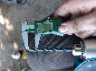
traction side
The traction side is the side that is pulled by the jackshaft. The slack side is the side with the hydraulic/spring tensioner. Try to pull up and push down the top of the guide assembly where the guide post is. There should be almost no vertical movement.
The traction side is the side that is pulled by the jackshaft. The slack side is the side with the hydraulic/spring tensioner. Try to pull up and push down the top of the guide assembly where the guide post is. There should be almost no vertical movement.
 -DW
-DW