IAC Voltage | Ford Explorer Forums - Serious Explorations

  • Register Today It's free!

IAC Voltage

Joined
July 1, 1999
Messages
13
Reaction score
0
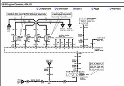
I'm trying to diagnose my intemittent idling problem (stalling and racing idle). According to Haynes, the input voltage (key on engine not running) to the IAC is 10.5 to 12V. Mine is reading about 4-5V. Does this indicate that something is wrong with my PCM or is Haynes wrong. Also the resistance of the IAC is 0 ohms, which is not what the Haynes manual says it should be.
I'm not sure what to check or replace next. Hopefully not the PCM. The IAC is less than a year old. I got it from NAPA, and I remember the guy telling me that there were two available for my X. Now I'm not sure I got the right one. Thanks for any help you can give me.

Travis


Join the Elite Explorers for $20 each year.
Elite Explorer members see no advertisements, no banner ads, no double underlined links,.
Add an avatar, upload photo attachments, and more!
.


Haynes is wrong, input voltage is 5V. Check the other wire with the key on engine off, optimal voltage is .96V


That's TPS voltage...IAC is Idle Air Control valve, and I'm at work and don't have my manual in front of me to check, but it's not the same as TPS voltage...


Oops yeah, brainfart. I have no clue why I read IAC as TPS.


I have a butt load of info for a 97...you didn't say what year your X is...hope this is useful:
 

Attachments

  • iac1.jpg
    iac1.jpg
    40.6 KB · Views: 765


iac2
 

Attachments

  • iac2.jpg
    iac2.jpg
    30.6 KB · Views: 751


iac3
 

Attachments

  • iac3.jpg
    iac3.jpg
    27.1 KB · Views: 713


iac4
 

Attachments

  • iac4.jpg
    iac4.jpg
    22.8 KB · Views: 713


iac5
 

Attachments

  • iac5.jpg
    iac5.jpg
    31.5 KB · Views: 695


iac6
 

Attachments

  • iac6.jpg
    iac6.jpg
    20.8 KB · Views: 679


iac7
 

Attachments

  • iac7.jpg
    iac7.jpg
    21.1 KB · Views: 693


iac8
 

Attachments

  • iac8.jpg
    iac8.jpg
    35.6 KB · Views: 661


iac9
 

Attachments

  • iac9.jpg
    iac9.jpg
    48.5 KB · Views: 676


iac 10 The schematic for the IAC circuit. VPWR is the red (R) wire.
 

Attachments

  • iac10.jpg
    iac10.jpg
    64.7 KB · Views: 847


Thanks for clearing the diode issue up

I'd been warning people who test these on a bench that they should be concerned about polarity. A lamp in series with the power will protect the diode in case they hook it up backwards. Otherwise the diode makes it a short and it burns up. Older manuals indicated an internal diode and later ones just showed the coil. Never got around to testing my 97 to see if the diode was there. Since this is a pulsed output, some digital meters may not read the voltage correctly. This is one case where an analog meter works better.


Back
Top