PATS code 15, no crank, 2 keys | Page 2 | Ford Explorer Forums

  • Register Today It's free!

PATS code 15, no crank, 2 keys

Its a induction coil / sensor for a pats bypass module
Look for a pats key under the dash hidden in a box hidden somewhere
Follow them wires

View attachment 425439
Thx! Looking at the diagram, should the two black wires coming from the ring be connected to the hidden box?
[/QUOTE]


Join the Elite Explorers for $20 each year or try it out for $5 a month.

Elite Explorer members see no advertisements, no banner ads, no double underlined links,.
Add an avatar, upload photo attachments, and more!
.


Thx! Looking at the diagram, should the two black wires coming from the ring be connected to the hidden box?
[/QUOTE]
Yep


Yep
[/QUOTE]
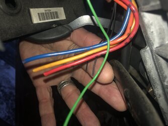
Hmmm, there are other wires under the steering column that also appear to have been snipped (see picture). Perhaps there was a bypass kit at one time and removed before I bought the truck? And I can toss the induction coil?

3CE6CCC9-E5CA-422A-BF1C-C5AA72778FDE.jpeg


Hmmm, there are other wires under the steering column that also appear to have been snipped (see picture). Perhaps there was a bypass kit at one time and removed before I bought the truck? And I can toss the induction coil?

View attachment 425446
[/QUOTE]
I don't see why not
Where do the new wires go?


Hmmm, there are other wires under the steering column that also appear to have been snipped (see picture). Perhaps there was a bypass kit at one time and removed before I bought the truck? And I can toss the induction coil?

View attachment 425446
I don't see why not
Where do the new wires go?
[/QUOTE]
Will check it out. In the meantime, i began some circuitry diagnostics this morning. When checking the 4 wire connector at the actual transceiver on the ignition cylinder, voltage (DG/WH) was ok but the ground (BK/LB)was reading 50 ohms. The pinpoint test suggests resistance should be below 5 ohms.


^ Good grief Charlie Brown! That's a drawn out process when a vehicle is needed operational ASAP.

Found it for '03, and '05, is going to be one of the two if not both applicable:
When performing the pinpoint test G as per the 2005 version, there is voltage from the dark green/white wire at the transceiver connector. However, when testing the black/light blue (ground), the resistance is greater than 5 ohms, in fact it’s reading 50 ohms. The action is to repair the circuit. Im guessing that would mean following the blk/lblue wire to where it is grounded. The wiring disappears under the steering column so this is proving to be a bit of a challenge. Any idea of where this wire travels and where it is grounded? Is it feasible to snip the wire just before the transceiver, splice a replacement wire and connect the other end to a good ground?


All I can tell for sure is it shows this Black/Light Blue wire joining into those from the instrument cluster, A/C function selector assembly, (or EATC assembly for automatic climate control), the multi-function switch, and the compass, then it tells me it's "G300" (see attached picture below) and to look at diagram "151-37" which provides this picture which suggests that everything mentioned above, connects multiple black/light-blue wires at splice S219 (but not where it is) , and then to (or at?) connector C215, then C215 onward is the final single ground wire for all the above, to the chassis ground point.

I'd check to see if that's corroded but otherwise (I did not read that procedure you mentioned but did look at the diagram) then yes, creating your own ground from the black/light-blue wire seems like something to try next. If running new wire, I'd just take it down to the G300 spot since that's where it's expected to be, in case any future work is done to it... or maybe for the time being any conveniently accessible ground point for testing, then if it works, spend the time to route the wire to the expected G300 ground point.

dash_ground_point1.png


All I can tell for sure is it shows this Black/Light Blue wire joining into those from the instrument cluster, A/C function selector assembly, (or EATC assembly for automatic climate control), the multi-function switch, and the compass, then it tells me it's "G300" (see attached picture below) and to look at diagram "151-37" which provides this picture which suggests that everything mentioned above, connects multiple black/light-blue wires at splice S219 (but not where it is) , and then to (or at?) connector C215, then C215 onward is the final single ground wire for all the above, to the chassis ground point.

I'd check to see if that's corroded but otherwise (I did not read that procedure you mentioned but did look at the diagram) then yes, creating your own ground from the black/light-blue wire seems like something to try next. If running new wire, I'd just take it down to the G300 spot since that's where it's expected to be, in case any future work is done to it... or maybe for the time being any conveniently accessible ground point for testing, then if it works, spend the time to route the wire to the expected G300 ground point.

View attachment 425703
Thanks for this! So, as per the diagram G300 is located on the driver’s side, close to the floor, just in front of the door opening?


I can't speak on the Explorer, but on my 1999 F150 I replaced the transceiver and it did not require reprogramming. I got a replacement transceiver from U Pull It for $10. They're available on Ebay as well, for more money of course.
^ Good grief Charlie Brown! That's a drawn out process when a vehicle is needed operational ASAP.

Found it for '03, and '05, is going to be one of the two if not both applicable:
Thanks so much for this, very much appreciated! When looking at page 419-01-04 of the 2003 version you provided, if I understand correctly, I’m checking for continuity between the PCM and transceiver/starter relay/auto lamp. WRT to pin 39, is it terminal 85 of the starter relay I’m checking for continuity? Also, for pin 22, where might the auto lamp sensor be located?
Thx again , there did appear to be a grounding issue at G300. I snipped both ground wires, stripped them, then reattached. Now getting a resistance reading of 0.00 ohms (perfect). Performed the pin point test G, however, Im stuck at step G 11. At this point, the instructions are to trigger a TRANSMIT SIGNAL COMMAND. I’m guessing that would require a different diagnostic tool than my AutoLink AL419? On the topic, I am unable to retrieve any codes with this tool. The tool suggests there are no codes found, not even stored or pending. I thought that perhaps each time I would try to start the vehicle, a code pertaining to the PATS issue would be generated. Not the case, so when performing the pinpoint test, I cannot clear codes since none are visible.
I followed pinpoint test G, not based on DTCs, but by the symptoms.
Anyone know if PATS code 15 is equivalent to DTC B1681?


It is terminal 86 of the relay. If you check terminal 85 instead, the resistance measured, even if nothing is wrong, would be higher, would be that of the wire, PLUS the resistance of the relay coil, which isn't always useful because the relay coil resistance can vary more than 5 ohms from one relay brand/specimen relay to the next.

I don't know for certain where the autolamp sensor is on an '04, but from hearsay it seems to be in the middle of the dash next to the windshield?

Without a scan tool that can trigger the transmit signal command, I'd "guess" the thing to try next is just put the key in and turn it, looking for voltage on that wire, then as the G11 instructs, if less than 5V, replace the PATS transceiver (I can only assume you did all steps leading up to G11 correctly).

An ODB2-only type scan tool, cannot read manufacturer specific codes that fall outside the OBD2 code set. This, and ABS, among others, are such codes. An OBD2 dongle linked to a client device (phone/laptop/tablet/PC/etc) running Forscan app should be able to read them. I don't know if it can issue the commands like transmit signal. Someone in Forscan's Forum probably knows.

I don't know for certain if a code 15 could be a B1681 but it seems like it could also be a B1601, or B1602. I could be wrong, and wouldn't go by that.
Thx. Step G7 of the pinpoint test is testing circuit 1216 (orange/grey) for voltage with key on. Since there was 12v present, instructions are to move to step G11, where that same circuit is again being checked for voltage, but with the transmit command being triggered.


You seem to be doing this correctly, as far as I can tell, but there is a limit to how much I can try to forsee remotely and I'm about at that limit. At some point after I checked for low ohms between all points in the circuit, I'd lean towards either getting a scan tool capable of the PATS codes, or pulling a transceiver from a junkyard and swapping it in, because it's low cost despite being "firing the parts cannon". If I was anxious to get this running, I'd put both plans in motion.

The scan tool I use for my '98 with an Android phone is a BAFX on Amazon.
Yes, im leaning towards swapping the transceiver. Is your scan tool capable of programming keys?


Yes, though I've never had to, yet. The Forscan forum has all the info, programing requires the windows app (so windows tablet/phone/laptop/PC link) with an extended license you can request there. The android app is not capable of programming keys, nor iDevices, only windows app with the extended license (free when requested) can do that.


I would use ForScan to reprogram the keys from scratch.
Hi. I’m interested in Forscan but have no idea which unit to purchase. Are there good and bad units on Amazon? Is there one you recommend? Thanks!


Any (usb) OBD HS+MS can adapter will be ok.


Any (usb) OBD HS+MS can adapter will be ok.
Thx. So I will be able to see and clear PATS telated DTCs,, assuming they are present, pending, stored, etc?
I own an Auto Link AL419 OBD II & CAN Scan Tool which indicates no codes are present. Should it be capable of reading and clearing PATS codes or is it good for only emission related issues.


You can simply purchase exactly the one from forscan site.

Your current scan tool possibly wont read the Ford HS (fast communication line) bus.


Join the Elite Explorers for $20 each year or try it out for $5 a month.

Elite Explorer members see no advertisements, no banner ads, no double underlined links,.
Add an avatar, upload photo attachments, and more!
.


Back
Top