How to: - Project Frankentranny - A4LD / 4R55E / 5R55E Hybrid Project | Page 3 | Ford Explorer Forums - Serious Explorations

  • Register Today It's free!

How to: Project Frankentranny - A4LD / 4R55E / 5R55E Hybrid Project

Prefix for threads which are instructional.
Rear output shaft support bushing/bearings...

The A4 uses a bushing mounted (pressed) in the rear of the case. Here is a picture of that bushing:
2713389_A4_output_bushing.JPG


The 5R uses a bearing instead. The inside diameter is the same as the bushing, but it is thicker than the bushing in the A4, so the hole in the case is larger. Here's the bearing:
27133MVC-010F1.JPG


The location of these bushings/bearings are shown in the next section.


Join the Elite Explorers for $20 each year.
Elite Explorer members see no advertisements, no banner ads, no double underlined links,.
Add an avatar, upload photo attachments, and more!
.


I found it curious that in the A4 the output bore used a bearing in the light HP applications but not the 4.0, and here in the 5R it is used throughout all apps. Also, in looking at the 5R specs, they contend the 4.0 had a 5 clutch pack in the direct clutch and 6 pack in the forward, the 2.5 and 3.0 litre apps had one less each. Was this from a 3.0 ya think? (oh and btw the rear race problem I had was 30 thou high, not 3). Great writeup! (And yeah it's real fun trying to take pics and doin/showin stuff... have to be rather clever in how you set some of those up so you can use the camera with one hand and at the same time be using the other hand for picture purposes - notice you never saw TWO hands in any of my pics <g>)


Back of case

Now we are all the way back in the rear of the case.

Here's the back of the A4 case (note that the output shaft bushing is already pressed out and is not in this photo):
2713333_A4_case_rear.JPG


Here's the back of the 5R case (the rear output shaft bearing is still in place in this photo - excuse the grime):
2713349_5R_rear_case_2.JPG


Here's the thrust washers that sit in the center behind the bushing/bearing (A4 on the left):
2713331_A4_and_5R_rear_washers.JPG

The A4 washer has a slightly larger outside diameter than the 5R washer, but the inside diameter is the same. I'm guessing that since the A4's gear is heavier because of the govenor and counterweight, it needed a bigger washer. The tabs fit into the depressions in the case.

These washers keep the next parts from rubbing against the soft aluminum that the case is made of (at least where the washers are - in a thrust fashion). Here is a pic of the A4's govenor unit mounted on the parking gear on the left and the 5R's speed sensor steel "castle" along with its parking gear (although in this shot you can't see the castle):
2713328_govenors.JPG


Here's a side view of the A4's govenor/parking gear (this actually shows the sealing rings and not the govenor):
2713329_A4_govenor_snout.JPG


Here's a side view of the 5R's speed sensor "castle"/parking gear (notice that there is obviously some scratches in the steel from a collision with...the case):
2713330_5R_output_speed_sensor_snout.JPG


The large lugs on the parking gear are engaged with a parking prawl, which locks into place so that the output shaft is held solid.

Here's a closeup view of the A4's rear bore where the govenor/parking gear ride:
27133345B_A4_case_rear_drain_closeup.jpg

The holes marked "A" are where the govenor gets and sends pressure. When the output shaft is stopped, the weight of the govenor doesn't overcome the force of a spring that is inside underneath the round weight, so it gets pushed out towards the output shaft (but can't come off to the inside because its travel is limited by the output shaft). When it spins fast enough, the weight opens an internal valve which allows pressure to activate the intermediate band, causing a shift from first to second gear. So if you have a problem with 1-2 upshifts in the A4, look for a sticky govenor.
The hole marked "B" is a drain. There is a sealing ring that keeps the fluid used to lube the rear bushing and rear thrust washer from interfering with the govenor pressure. There are another couple pics below to show where this drain leads.
The space marked "C" is where the lube channel goes up to the space around the output shaft bushing. When removing the rear sprag race, this space must not be penetrated.
The channel marked "D" is a channel that allows lube that is pumped in from the bottom of the case to flow around the bushing (and into the holes in the bushing) and out the three evenly spaced slots on the inside of the case snout (for lubricating the low/reverse planetary gear set, washers, and sprag).

Here's a shot of the drain goes...first out the little hole here:
27133346_A4_case_rear_drain_bottom.JPG


and then back into the pan from this opening (there's another one back there as well, but I only could get my finger in one at a time):
27133347_A4_case_rear_drain.JPG


I decided to open (enlarge) the channel that feeds the rear bushing and all the rear components lube (more on my modifications later), and this is the hole that does this (the one with the light clearly shining through it):
2713336_modified_rear_bushing_lube_hole.JPG

The two holes on each side of this lube hole (the ones with a little light shining through, not the bolt hole) are the ones that supply/return from the govenor.

The last thing to compare in the rear is the case vent. It comes off the top and is the same on both the A4 and 5R:
2713335_A4_case_vent.JPG


Now we get back to the 5R and its rear bore. Here is a closeup of the proximity sensor that sends a pulse to the computer when a spoke on the "castle" passes by, which allows it to compute the output shaft speed (faster pulses equals faster speed, same 2-wire operation as the input speed sensor mounted ont he center support):
2713350_5R_output_speed_sensor.JPG


Here is where it is connected to the outside world at the back of the case on the top (excuse the grime :D ):
2713350_5R_output_speed_sensor.JPG


and here is a closeup of the connector showing that it is a simple two pin connector:
2713352_5R_output_speed_sensor_connector_2.JPG


There is a drain on the 5R as well...quite a bit larger than the A4's (probably because there's more space for it):
2713348_5R_rear_case.JPG

Notice that there is SEVERE scarring of this bore where the "castle" has hit/rubbed/scarred/worn this bore. I don't know why, but the evidence is there that it did.

Here's a shot of the 5R case vent (the vent is out of focus - sorry). Like I said, same as the A4:
2713353_5R_case_vent.JPG


The rear lube is fed the same way as the A4, up from the bottom and in the same location.

The parking mechanism is the same (the rod that sticks out from the back). More on this later in the post.


At the very back there is the extension housing. Both of these trannies are 4X4 units, so they have a short extension housing before they get bolted up to the transfer case.

They are the same. Here's the front (tranny side with a place for the parking prawl):
2713326_A4_extension_front.JPG


and here's the back (transfer case side):
2713323_A4_extension_back.JPG


If you look at the bottom of the back, you see a dam and a hole in it. On the automatics this location is wet and doesn't have a drain. I've seen where the manual transmission extension housings have a drain here (at the flange that connects to the transfer case). Since this area is exposed to tranny fluid (but not normally submerged in it), people have fewer problems with getting the transfer case off, because the output shaft isn't corroded/grimed/gunked to the input of the transfer case.


Now that we've gone front to back with the internal hard parts, it is time to compare the friction bands (three total in each transmission), servos (two in each), and associated hardware (levers, pins, anchors, etc.).

I'll start at the back and work forward. This means the first thing is the parking prawl and spring. They look the same to me. The only difference I can see is that the one from the A4 is marked with an indented "N" on one side and the one from the 5R is marked with a raised "N" in a depressed circle. There is a picture below with all of these small metallic parts.

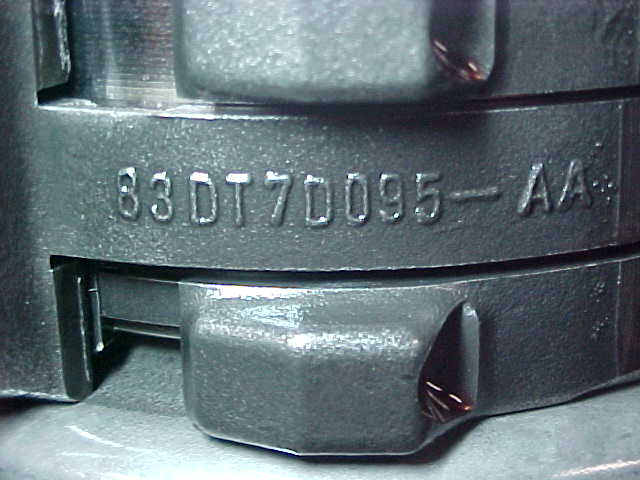
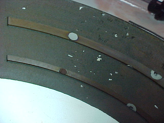
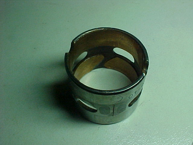
Next is the low/reverse band. They are the same. I don't mean kind of the same...I mean the exact same part number. I think that they have been making this band the same since '83 (from the part number). Here it is (this is off the 5R - chosen because the numbers showed better in the photo):
2713313_5R_lowrev_band.JPG


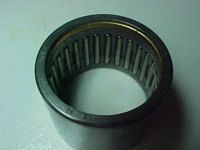
Now the reverse piston that actuates the low band. Both had close to the same part number. They both have the same diameters for both o-ring seals. There are a couple of differences, but at this point I'm not sure this is an as-manufactured condition or the result of some damage. I'll update this part when I get them torn apart and see what's going on.

Moving forward in cases we get to the intermediate and overdrive servos. These are the pistons that apply force to the friction bands that stop the intermediate drum and overdrive drum from spinning. Each servo has an apply side and a release side. The servos are made in different sizes, denoted by a two letter code, and work only with their own specific sized cover. Here is what we know: BB is 1.945" in diameter, AB is 2.100", and ZC is the largest with a diameter of 2.300". There are five smaller sizes, but as far as I'm aware, they weren't used in the 4.0L version. The larger the piston, the more force is supplied by the piston (if the pressure is the same). In the A4, the BB sized servo was used on the intermediate (further back), and the AB sized servo was used on the overdrive (further forward). In the 5R, the AB sized servo was used on the intermediate, while a ZC was used on the overdrive.

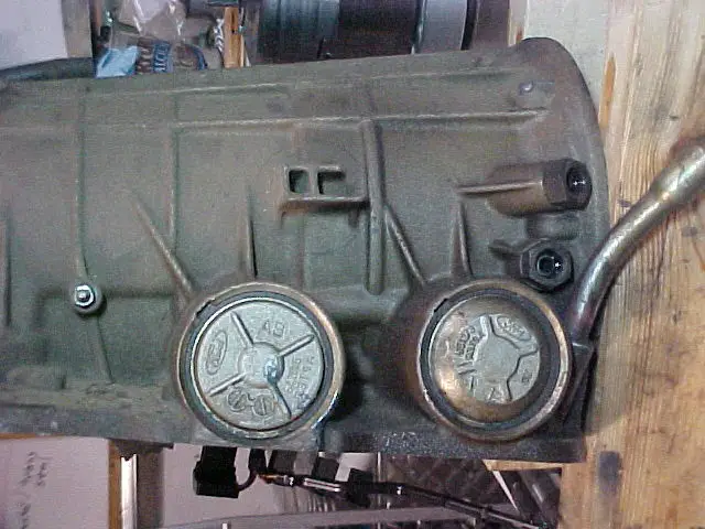
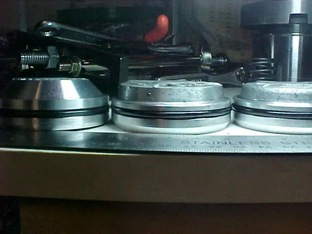
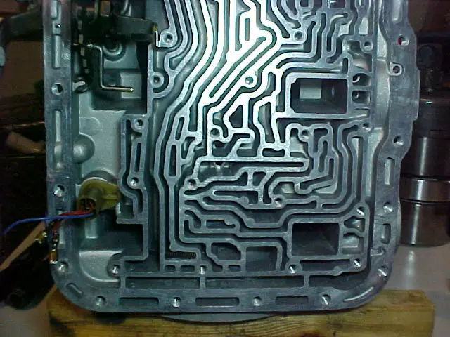
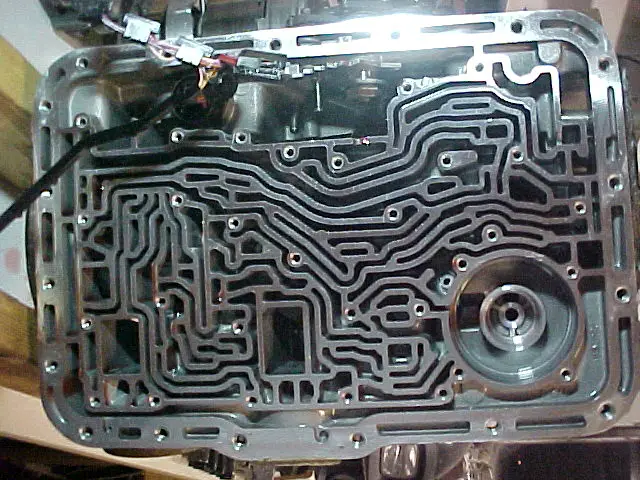
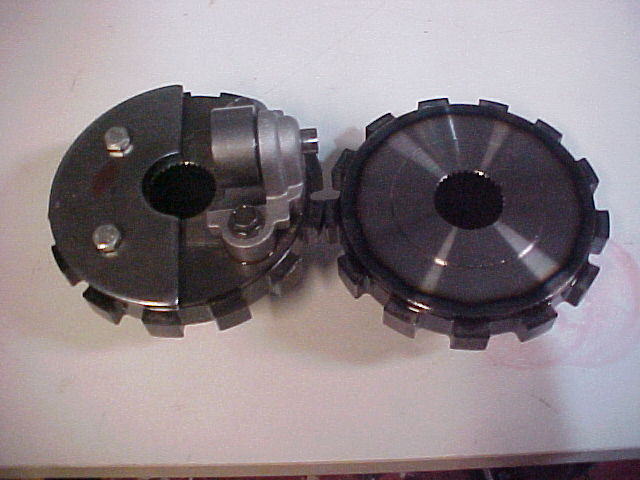
Here's a picture of the servos with their covers on in the 5R case:
2713359_5R_right_front_case.JPG


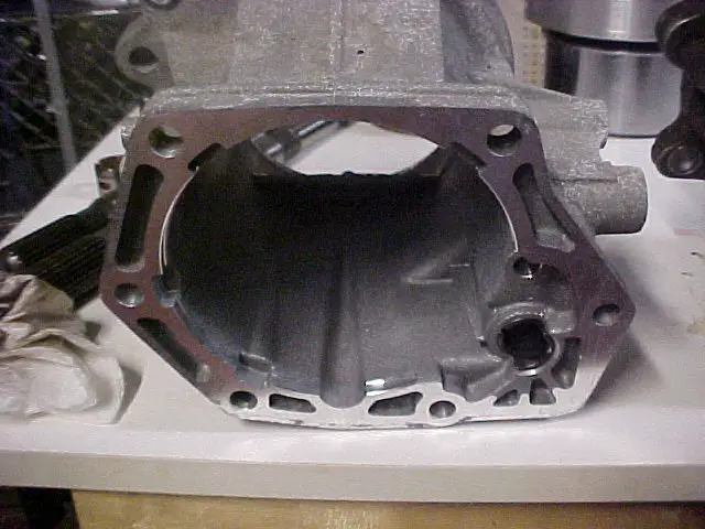
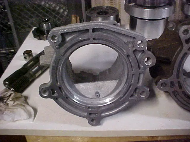
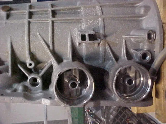
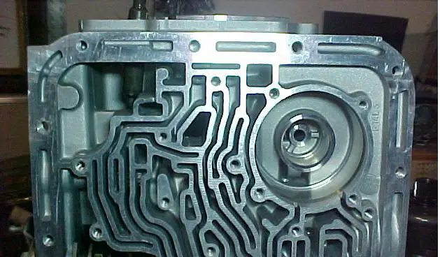
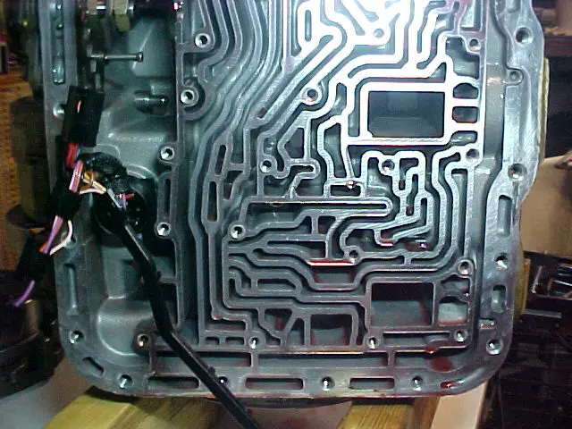
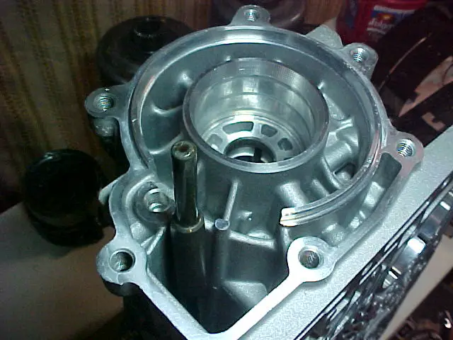
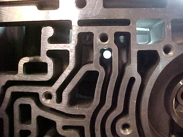
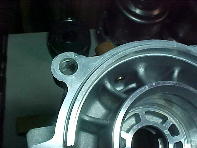
Here's a picture of the A4 case without the servos installed:
2713343_A4_right_side_1.JPG


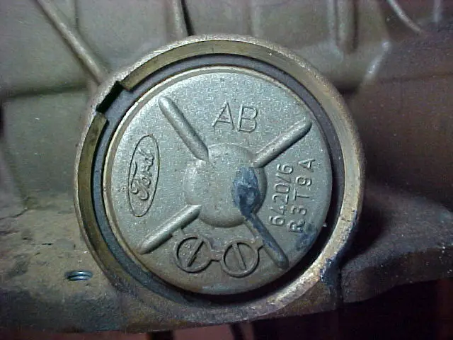
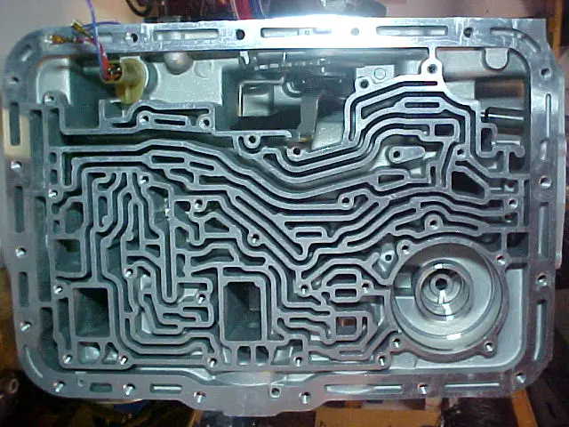
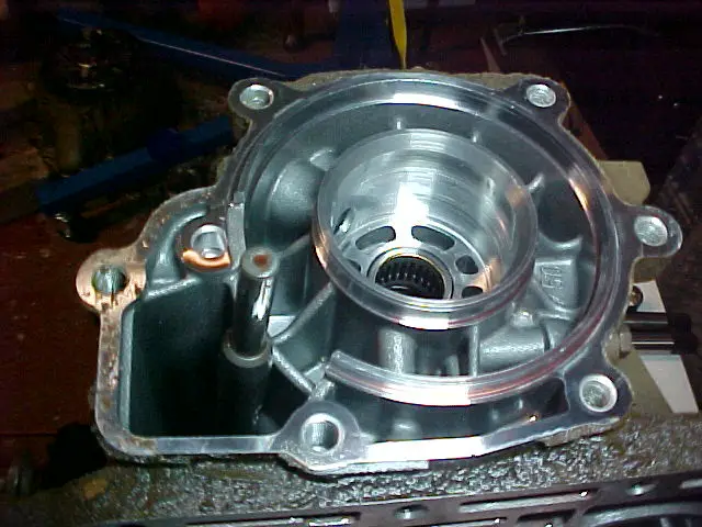
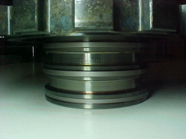
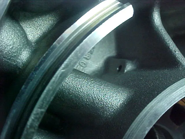
Here's a picture of the 5R intermediate servo cover installed in the case (note the AB on the cover):
2713361_5R_intermediate_servo.JPG


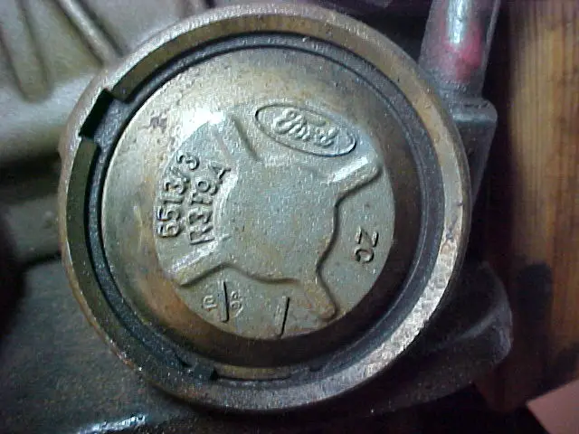
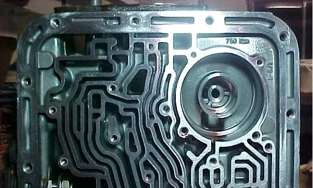
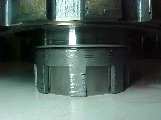
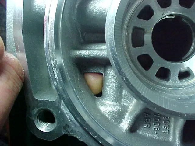
Here's a picture of the 5R overdrive servo cover installed in the case (note the ZC on the cover):
2713360_5R_OD_servo.JPG


More servo pictures will be posted later.

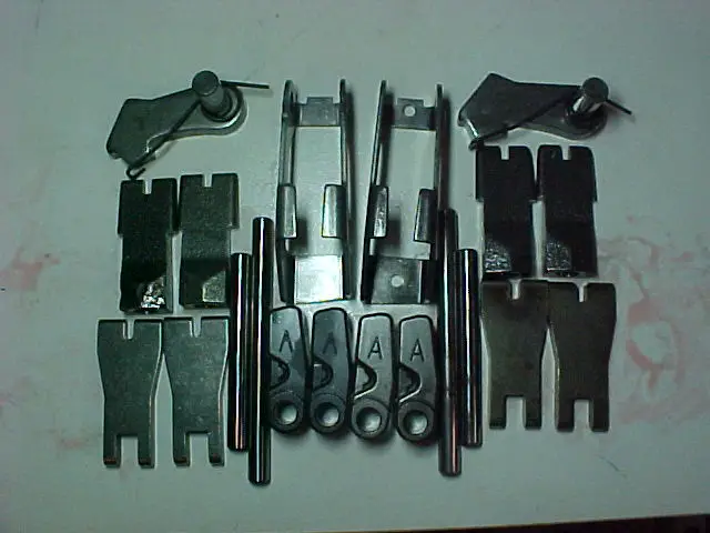
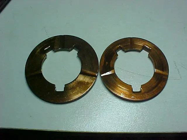
When the servo is activated, it applies force to a lever, and in this case both sets of levers had the same lever distance, denoted by the letter A on all of them. One of the things I noticed that was different was that the levers from the 5R didn't show as much wear where the servos applied force. The A4 had 125K miles and the 5R only had 90K, but the difference in wear is still an outstanding factor. I believe that the levers from the 5R are different in that they use a hardened steel (not sure if it is case hardened, through hardened, or an alloy, but it takes more force from bigger pistons/servos with a lot less wear). Here is a picture of the parking prawl and spring, band levers, anchors, and accessories (A4 stuff on the left, 5R on the right):
2713322_band_hardware.JPG


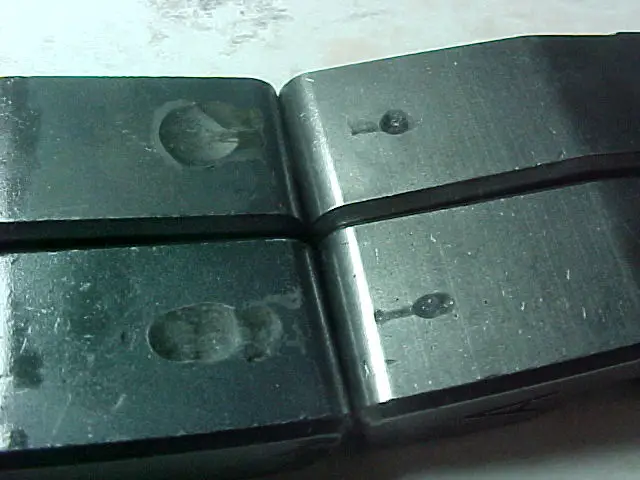
Here is a closeup of the wear marks on the levers (A4 on the left):
27133225_levers.JPG


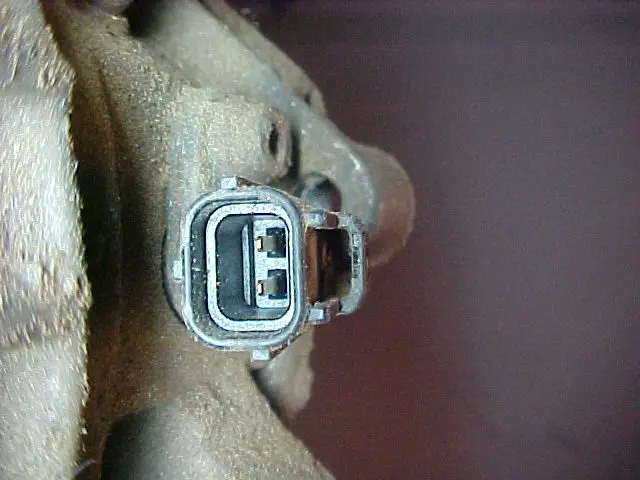
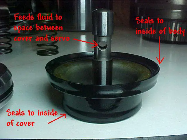
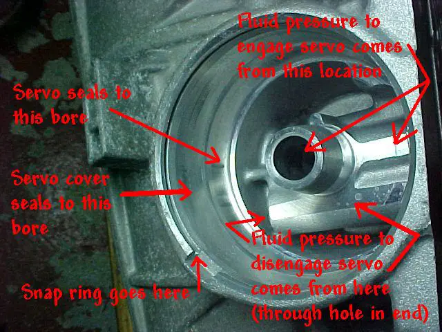
Now that we've looked at the levers, let's look back at what pushes on the levers - the servos. Here's a picture of a typical servo and what seals against what:
27133Z-016FB1.jpg


Notice that there are two seals on each servo. The one that seals agains the cover applies force to the lever (engaging it), and the one that seals against the body moves it in the opposite direction (disengaging it). Fluid gets between the servo and the servo cover through the hole in the stem (or rod) and flows through the hollow stem up to a hole in the top.
27133Z-014FB1.jpg


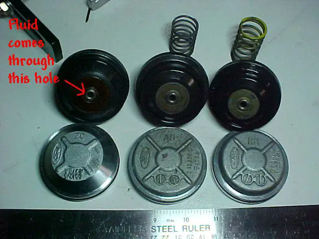
Notice that I have them arranged starting from the left with the largest (ZC on the cover) and going to the left with the smallest (BB on the cover). It is the seal that seals between the servo and servo cover that changes, as the seal to the body of the transmission as well as the stem sizes are the same.
I only have two springs from the A4 showing, but I'll show the other spring when I get it removed from the 5R case. These springs help to push the servo out into the deactivated position.

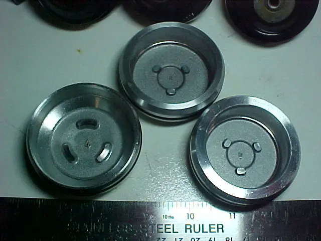
Here's a pic of the inside diameters of the servo covers (ZC on left):
27133Z-015F.JPG


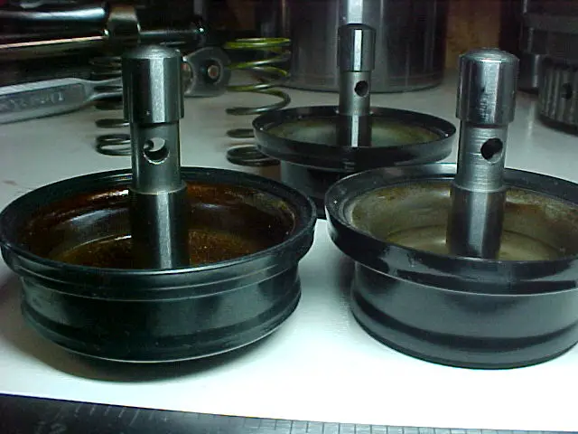
Here's a pic of the three sevos next to each other (ZC on the left front, BB in back):
27133Z-017F.JPG


Here's a shot of the sides of the servo covers (ZC on the left):
27133Z-018F.JPG

Notice that the cover also has a o-ring seal to keep fluid in the case.

Now we'll take a look at where these servos fit into the case.
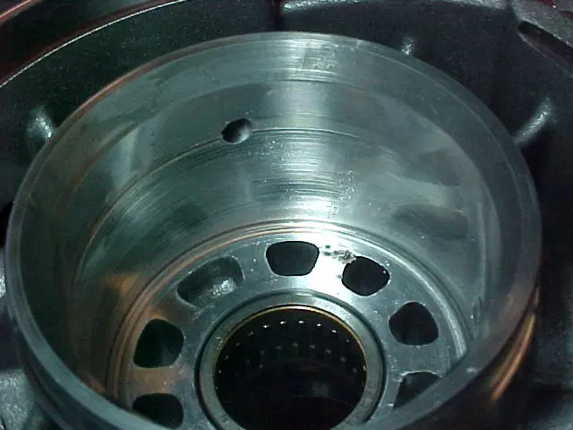
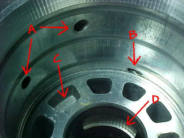
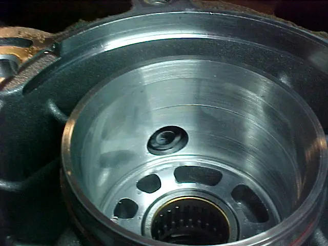
Here's a pic of a servo bore in the case (they are pretty much the same in both locations on ech case, and the same case to case):
27133Z-021FB.jpg


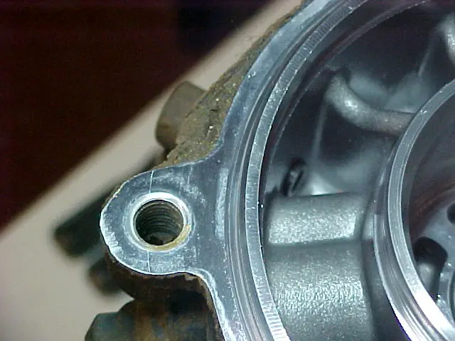
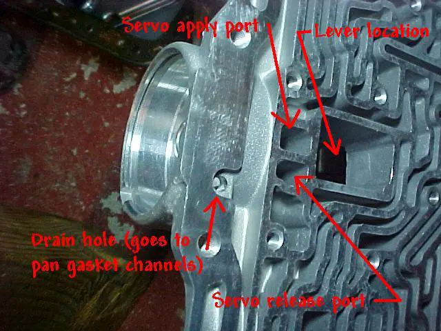
Here's a pic of the intermediate servo locations in the case:
27133Z-019FB.jpg


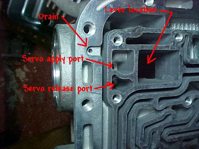
Here's a pic of the overdrive servo locations in the case:
27133Z-020FB.jpg


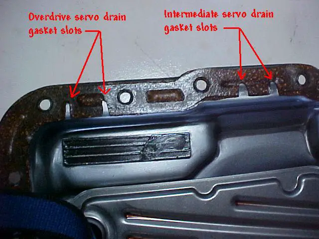
Notice that both have a drain that appears to be located where the pan gasket sits. The intermediate drain is smaller than the overdrive drain (the intermediate servo has more pressure, therefore more potential leakage and larger drains). The pan gaskets and the pan are the same for the A4 and the 5R, and both have small channels cut into the pan gasket to let the (supposedly small amount) fluid that gets by the servo/servo cover seal drain back into the pan (and it is this leaked fluid which the o-ring on the servo cover serves to contain).

Here is a picture of where the pan gaskets have channels in them for the drains:
27133A-026FB.jpg


(Update 2)
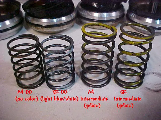
Each servo has a spring to help push it back into the cover. This might just be a safeguard so that if you kill the engine in a gear where a band is applied, when you start it, the band is disengaged. Here is a picture of the springs:
27133S-015FB.jpg

I noted the colors that I had, but just FYI Glacier991 had some different colors for his spings in his A4 rebuild (as documented in the A4LD rebuild diary).
(end of Update 2)

Next is the intermediate and overdrive bands. I'll post more here later after I take some more pictures.

(Update 1)
Overdrive and Intermediate Bands

The bands function the same for all transmissions: they selectively apply pressure around a drum to get it to come to a stop and keep the drum from rotating when required. There have been two distinct band styles for the A4’s, namely a double-wrap design (for a short period) and a single-wrap design. The single-wrap kinds are the only ones I have to compare data on, but to see a picture of the double-wrap design, look here at Glacier’s A4LD rebuild diary - part 3, page 4 (top of this link):
http://www.explorerforum.com/forums/showthread.php?t=103666&page=4&pp=20

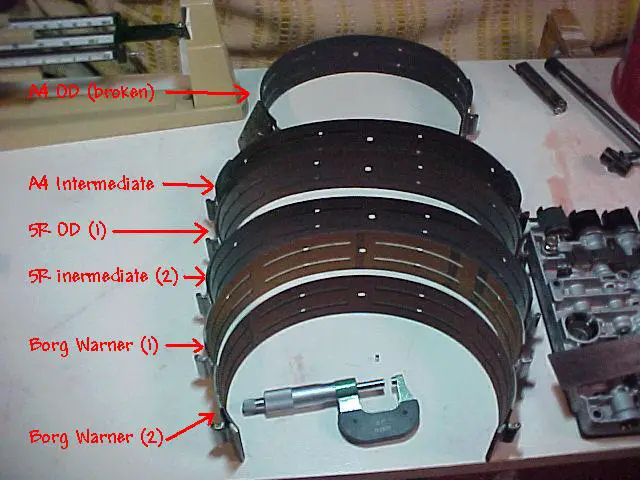
I have in my possession six bands: two of the Ford originals from the A4, two of the Ford originals from Jefe’s 5R, and two Borg Warner aftermarket replacement bands (same box part number but quite different). I’ve measured thickness and mass data on each one listed below, and only one stands out from the rest as being superior (IMO). I don’t have any data on the Raybestos brand bands, so I can’t vouch for their properties.

So what makes for a good band? Two things stand out above the rest: having enough friction material to outlast the other parts between rebuilds and not breaking into two parts.

All friction material is meant to wear down. This wear is the sacrifice of being able to dissipate energy (reduce the rotational inertia, a form of kinetic energy). This opposing-force energy is created by molecular separation, where in the best case (least wear) a single molecule is pulled from its adjoining molecules, and in the worst case (most wear) where chunks of material is ripped away (leaving the bonds internal to the chunk of material intact). Either way, it involves separating molecular bonds. With this concept (roughly) explained, heat is the byproduct of this molecular separation. If there is no heat generated, there is no braking force applied. For example, if the metal plate or drum next to the friction material is so smooth (glazed) that there isn’t enough “bite†to wear away friction material then the opposing force is reduced (and slipping could occur).

Now, I’m pretty well set-up in my garage, but I don’t have the capacity to quantitatively measure the molecular properties of the friction material used in these bands, so I’m going to have to compare them on the basis of thickness of friction material an ASSume they have the same friction properties ;) . Since this friction material is weak in tension, it is bonded to a metal band in all locations, but there are lubrication cannels (and holes) in the bands where I can accurately measure the thickness of the metal band. That means that in order to get a thickness value for the friction material, I measured the entire thickness and subtracted off the metal, so it is a derived value (as opposed to a direct measurement).

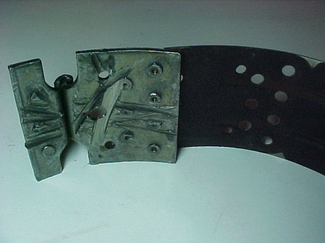
The thicker the metal band, the more tension it can take without breaking and the more heat it can sink (before transferring it to the tranny fluid), but there is a limit on how much thicker the band can be because the thicker the band, the stiffer and less conforming (to the shape of the drum) it is. The ends of the bands have anchors that are attached with rivets, and the thicker the metal band is, the more force the band can sustain without rivet pull-through (where the rivet head pulls through the band metal). If the friction material is worn away to where the heads of the rivets are ground off, it doesn’t matter how thick the metal band is, it is pulling apart (example picture below).

O.K. – time to compare some bands. Here are the six bands that I have:
27133A-014FB.jpg


The first band end – the broken overdrive band from my A4:
27133A-020F.JPG


The second band friction material – the contaminated intermediate band from my A4 (metal particles embedded in the friction material):
27133A-019F.JPG


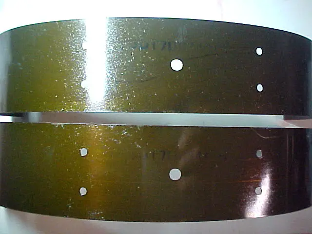
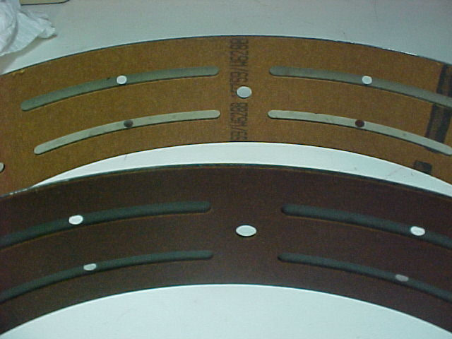
The third and fourth band backs (steel) – the 5R overdrive and intermediate band:
27133A-018F.JPG


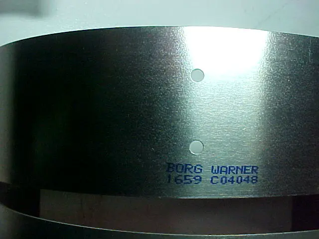
The fifth band back (steel) – the first Borg Warner band I received:
27133A-017F.JPG


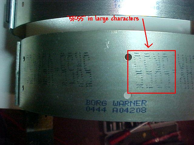
The sixth band (steel) – the second Borg Warner band I received:
27133A-016FB.jpg


The fifth and sixth band’s friction side (fifth or first band on top):
27133A-015F.JPG


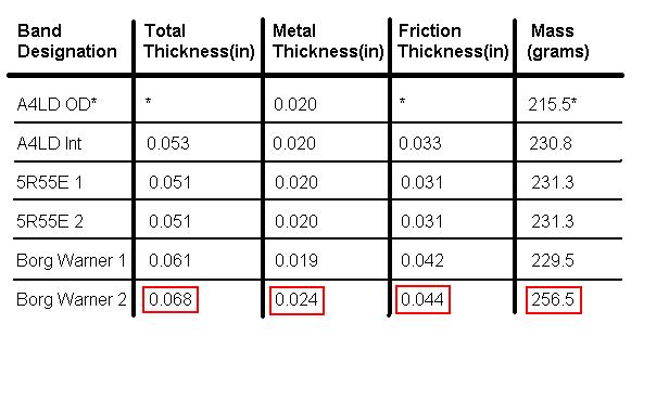
Here's the data on the bands:
27133A-chart1.jpg


* - value isn’t valid due to the existing damage

Something that should be mentioned is that while the A4 and 5R bands were previously soaked in fluid (which might add to the mass value slightly), the Borg Warner bands were completely dry. Another thing to consider is that the A4 bands had 125K miles on them, and the 5R bands had about 90K miles on them.

You can see which one I like the best, and for Frankentranny I’m going to try to get a second band with the big “5R55†letters printed on the band (I only have one at the moment). The two Borg Warner bands were ordered as the same part number from TranStar, so I’m not sure if the change was a running production change or what the deal is there. One had a date code of early August and one had a date code of late August on the box, and the first band cleaned out their stock on hand, so it is possible that when distributors run out of the first kind, the second kind will be what is dealt.


Brain said:
Here's a side view of the 5R's speed sensor "castle"/parking gear (notice that there is obviously some scratches in the steel from a collision with...the case):
2713330_5R_output_speed_sensor_snout.jpg


2713348_5R_rear_case.jpg

Notice that there is SEVERE scarring of this bore where the "castle" has hit/rubbed/scarred/worn this bore. I don't know why, but the evidence is there that it did.
Perhaps from putting it into park while moving? I know I did that far too often because of the Atlas T-case. Think that'd be enough to shove it ****-eyed and contact the case?


Yep, I think that makes sense Jefe. Thanks for the reason for the scarring. :thumbsup:


I'm going to try to get a double-tall pic composite to work here for showing the bottom of the cases.

Here's the A4:
2713337B_A4_case_bottom_1.jpg

2713338_A4_case_bottom_2.JPG


And the 5R:
2713362C_5R_case_bottom_1.jpg

2713363_5R_case_bottom_2.JPG


Here they are again smaller so that they fit into a single photo.
A4:
2713339_A4_case_bottom_3.JPG


and the 5R:
2713364_5R_case_bottom_3.JPG


There aren't nearly as many changes in the case portion of the valve body as I was expecting. I count only three. But I soppose the case functions haven't changed, only the way they're activated.


Eureka!!

27133X-014F.jpg


After I got the rear race in place (see the updates...there have been several), I just couldn't stand the temptation of placing the hard parts in the case and seeing if the two end play values came out OK. I only have the end play values for the A4 (.012-.022" for the rear, .007-.025" for the front), so if anybody has a manual/literature that shows the values for the 5R I'd really like to know if these values have changed.

My rear end play value came out to be 0.015" (.014 and .016), and the front was 0.027" (out of spec but able to be brought into spec w/ a simple selective washer change). On the front there was a 0.072" thick plastic washer with a marking of NA on the back (different numbering scheme than the selectives for the A4), meaning it started at zero-time as a 0.074" thick washer and was worn down by 0.002" after over 90K miles. The plastic ones that fit easily over the pump snout roller bearings come in a variety of sizes from 0.055 to 0.095" thick (not quite as much choice in sizes as the A4's metal ones, but I'm close enough in this case to make it work).

Any help with the end-play values would be greatly appreciated. If the tolerances allow for it, I might even substitute a Torrington bearing where the #1 selective washer is located, leaving even fewer thrust washers in the case than the 5R. :D It time to one-up Ford's engineers!

I'm still not done updating/adding to this thread. There is still a lot of work to be done on the tranny, but this realization of getting the hard parts to fit in the case with minimum modifications is a real milestone.


Very interesting, and thanks for your hard work!


Brain... rear case clearance - 55R... .008 to .021, front case clearance....007 - .028


excellent...means it's in spec as is. I figured the ranges would be tighter because of the bearings, but it lloks like one is tighter and one is looser. Hmmm. I'm probably still going to bring the front in a bit tighter (thicker #1 thrust washer). Thanks a bunch.


Well well.... once we cross into that sacred territory known as the 5R55, it turns out there ARE some upgrades, even amongst THAT family.... maybe Stocki who said there was a strengthened tranny being used in europe knew more than we all thought. Here is the progression...

5r55E comes out in 96... in 99, FORD makes the 5R55N, which goes in the (hold your hats) Lincoln LS and in the JaquarX200(!). Looks like the changes were in frictions and steels, and planetaries and sun gears and sprags.... hmmm... all weak links. I'm investigating what all they did.

Then, in 02/03 they came out with the 5R55W, which is in the Explorer for those years. Again changes in planetaries, filter(?) and a few other hard parts, AND! hi perf bands (THAT SHOULD BE REVERSE COMPATIBLE ALL THE WAY BACK INTO THE A4LD!!) So more work remains to be done....


FYI. I've updated some pretty important stuff (IMO) about the OD retaining ring on the first page (planet carrier section). Kind of a rant, but well deserved. I also added an update on the OD piston modification.


Brain... I went back and read what you updated. I annoint you the KING of DIY trannie engineering. WOW. Great work. At the risk of sharing something publicly.... Brain and I chat frequently bouncing ideas around. He ALWAYS has an asnwer to some of my dumb questions.... often also providing additional thoughts and ideas far beyond what I would ever have considered. I think that we I could find a 5R55N and 5R55W to compare, and with what he is doing, we really COULD design a near bulletproof A4LD. For my 2 cents... I think the A4 has it all over the 4R and 5R in some ways. What ways ? The lack of solenoid control.... those buggers beg to plug up to be contaminated.... I'm thinking.... the trannie guts from a Jaguar in a humble first gen Ex!!!!

Ain't DIY exploring great? THANKS BRIAN !


Just FYI...I updated the overdrive and intermediate band information above. If anybody else has band data to contribute, please feel free.


Brian... I ran across something - it may be something you already know, but it might be helpful... in the 5R, FORD had TWO intermediate drums and TWO Forward clutch cylinders. The book shows a 5 plate forward clutch drum and a 6 plate forward clutch drum (FORD #'s F77Z-7A360-CF and F77Z-7A360-EO, respectively. The intermediate it just lists as ONE groove and TWO groove (not sure what that relates to) they are FORD F77Z-7D044-CF and F77Z-7D044-AE respectively. U might look into that.


Thanks for the info Glacier. Are the part numbers you gave for the intermediate for the drum or the piston. I ask because I posted an update to the intermediate drum portion (currently update #2 on page 2) and listed the part numbers for the drums, but they had the numbers XL2Z-7D044-CA for the drum using the small piston used on the SOHC and XL2Z-7D044-AA for the drum using the larger piston used on the DOHC (which is the one I have), which means that we have different prefixes and suffixes to the part number of 7D044.

The forward clutch drum had a part number of F77Z-7A360-EE, so now I'm totally confused about the "right" part numbers. I have to confirm that this is the number stamped on the drum, so I'll get back to this when I have a few minutes. :confused:


Join the Elite Explorers for $20 each year.
Elite Explorer members see no advertisements, no banner ads, no double underlined links,.
Add an avatar, upload photo attachments, and more!
.


On the intermediate, I cannot be sure, but the idea of a "groove" identifier is more consistent with a piston for sure....sorry to add to confusion.... but in the end maybe there will be more light! I also found it interesting that the 5R55W, in addition to a unitary case (e.g. no separate bellhousing) FORD fused the parking pawl gear onto the output shaft...one piece... finally leaving the A4LD/C3 origins for good. Clearly THAT isn't backward workable... but I just thought it interesting.


Back
Top