Thought this would help. Apology's for the excessive length.
Figuring out the 5R55 Alphabet
The following material focuses on the inspection and diagnostics of 5R55W/S
transmissions. Although the 5R55N is similar, only a few parts are interchangeable
and most others can create problems if installed in a W/S unit.
The N unit was used from '99-'02 in Jaguar S with 3.0/4.0 liter, Lincoln
LS and Thunderbird 3.0/3.9 liter. The N was replaced by the S in 2003 in
the Lincolns and T-Birds. The W showed up in Explorers and
Mountaineers for '02-'03 before giving way to the S in '04-'05 models.
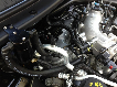
An external visual inspection will reveal the N has two cast bosses, just behind
the intermediate servo cover, closest tapped for PCC. The W/S has only
one boss for the PCC pressure port (see Figure1). If the unit is in the vehicle, you cannot see this but you can feel the difference.
With the oil pan removed, the N will have a base plate similar to the 4R70W covering the lower valve body along with a reverse
pressure (RP) switch. The 5R55W/S solenoid
will not have terminals for the RP switch and
the circuits are different. This article will
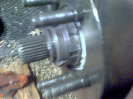
address the W (24-tooth OD sun gear) and
the S (38-tooth OD sun gear) even though
hard parts vary.
Common problems
Valve body and case bore wear
The point of excess valve-to-bore clearance
can be very subtle. For a quick visual indication
on the condition of a 5R55W/S valve body,
I suggest you start with the TCC modulator
bore 9 (see Figure 2), followed by the main
regulator bore 2 (see Figure 3). These tend to
wear first, due to their activity. You can
review these Sonnax repairs on pages 118
and 119 of this catalog.
As the cycle rate (higher in city traffic) progresses,
the VFS 1, 2, 3 modulator bores wear, reducing clutch and servo pressure. With adaptive strategy, the PCM
can compensate, but after excess wear, gear ratio codes or slippage
occur. Often the solenoid or the servo pin bore is blamed
as the culprit, but actually the VFS modulator valves cannot
supply enough pressure.
Solenoid manifold
The solenoid assembly appears to interchange between the
N/W/S, but the critical components are the base plate and
the filter (see Figure 4). If the base plate or filter are mixed,
the unit will lose reverse, TCC apply and solenoid oil pressure.
The W/S components are pictured in Figure 4.
The filter, which is part of the gasket, lives under the aluminum
base plate and is a serviced item. If you plan on reusing it,
keep it far away from solvents or the silicone bead will never be
the same size. If you replace it, compare the old and new filters.
The solenoid is often accused of creating a loss of reverse,
flare 1-2 or 2-3, or delayed forward. Even though replacing
the solenoid appears to eliminate the problem, the cause can be overlooked. Two root-cause issues follow: fluid that degraded
the solenoid, and a loss of prime.
The fluid problem in the 5R55E, W, S and N units was caused
by a factory ATF fill using an early Mercon V, prior to May 2005.
Ford released an interim additive package (4L2Z-19B546-AB,
fluid XL-11 with bulletin FSA 04B22) to install into customer and
new vehicle inventory. The final resolution was to use a revised
Mercon V (XT-5-QM) in a black quart container. If a service is
performed and any trace amounts of questionable fluid are not
removed, the service life of the next solenoid could be reduced.
A malfunction in a replacement solenoid can be traced to a loss
of prime in the VFS solenoids. These are tested and shipped
with fluid, but after handling, this lubricant drains off. Before
installation of the assembly, fill the circuits with the new
Mercon V or the XL-11 additive and pull the fluid through
the solenoid with vacuum. If the solenoid does not function
properly, run the vehicle until hot, allow a cooldown and
road test later.
You should also note that Ford units manufactured after 2002
have adaptive strategy, and a relearn should be performed along
with a solenoid service. Don’t forget to inspect the grounds
at the battery, the PCM, and clean the mass airflow sensor.
TCC slippage and converter failure
A common problem with the 5R55W/S is excessive TCC slip,
converter failure or noise. It’s important to understand that
converter release oil holds the TCC piston off the cover, supplying
charge pressure, then flows to the cooler. This release oil comes
from the converter regulator valve, and is limited to 130 psi.
As the command to apply TCC occurs, fluid from the solenoid
flows to the modulator sleeve (see Figure 5) and the end of the
TCC control valve. This solenoid pressure is supposed to be limited to
72 psi by the solenoid regulator valve (see Figure 6).
If altered or the solenoid regulator bore is worn
(inboard end), the pressure continues to rise at the
modulator valve sleeve. Higher pressure reduces the
slippage, but can cause TCC piston deflection and
converter failure.
How can the TCC piston deflect at 72 psi? Once the
TCC control valve strokes, modulated line pressure
is now the converter apply pressure. Release oil has been
redirected to the cooler circuit. Whatever line pressure
is available (160-250 psi plus) can be modulated via
the TCC solenoid and sleeve to control slip RPM.
If you work through this a few times, you can see how
valve body wear and modifications affect the TCC
clutch and converter. Another small but important
detail in this design is the back pressure valve (see Figure
7). It maintains 8 - 12 psi on the release oil to assist/allow
in controlling TCC slip and lube pressure.
Testing Valve body WAT
The Wet Air Test is an effective method for identifying
the condition of the 5R55N, W and S valve
bodies. This test can be performed in the vehicle or
with the transmission on the bench. When the valve
body is in good condition, the valves will stroke and
there will not be excessive leakage past the valves or
bubbling from the exhaust slots. It should be noted
that excessive bore wear, visualized as leakage
around the valve or slot, can aerate the fluid during
operation. This aerated fluid (suspended bubbles)
will create an excessive fluid level that then vents
from the case or causes erratic pressure.
Remove the solenoid base plate and reattach it over the
separator plate. ATF, along with low air pressure of 40-
60 psi, can be injected into the circuits (see Figure 8).
Converter feed, thermal element
and cooler flow testing
Fluid exiting the converter passes over a thermal element,
which starts to open when converter temperature
reaches 125º Fahrenheit. Prior to reaching the full
open/inward position, the fluid is circulated within
the unit for lube and there is no external cooler flow
In fact if there is any, it’s coming out of the
top/return to case fitting. Under normal conditions,
the opening requires considerable run time, during which it will not snap like a shift valve. When it does open,
the converter charge purges, reducing internal pressure, leaving
a void to be filled with cool fluid. The cooler fluid retracts
the thermal and the process can start over, causing erratic
fluid level and in some situations, converter overheat.
Once the unit is up to operating temperature, you can monitor
the converter command and valve stroke by the spike in
cooler flow. If the TCC modulator bore, TCC control valve
bore or the solenoid/gasket leaks, the change in flow is very
subtle.
If flow is always low when not in lockup and reduces significantly
in reverse, the pump line control valve may be sticking
open, the pump may be misaligned or the gear pocket worn.
Isolate pump noise with delayed engagements
The line control valve located in the pump has been known
to create a hydraulic resonance or to stick open. A plunger
stuck open exposes the output to pump inlet/suction, resulting
in delayed engagements. Once the RPMs come up, the pump
volume may exceed the leak and engagement comes back. A
plunger that will not open will reduce fuel economy, increase
pump body wear and could elevate line pressure in reverse.
If the transmission is in the vehicle and suspected of a line
control stuck open, place the selector into reverse and disconnect
the wiring to the solenoids. This results in maximum line
pressure and in many instances will hydraulically force the
plunger shut.
Do not sustain high RPMs or a long test as the servos and
seals sustain excessive pressure.
If the pump has been removed, supply 100 psi of air into the
port shown in Figure 9. If you hear a “pop” noise, the plunger
is stuck open. During the air test, no leakage should be escaping
from other circuits. If it does, the canister/housing is
loose in the bore, which will reduce pump output and line
pressure. If the line canister is on the bench, side load the
plunger as you push it down. No catch or edge should be felt
(see page 121).
Isolate converter noise
The 5R55N/W/S units have a TCC piston that floats
through the cover. In Figure 10 you can see the load springs
and the mating tooth patterns. Frequently and even with new
converters, excess interference and lack of spring load results
in a rattle, prevalent in neutral. This rattle is very difficult to
isolate and can be related to the flex plate, the inspection
cover, the camshaft sensor, the line control valve (review
above) or the converter piston.
These units require a flex plate alignment tool and during that
process the OEM paint/balance marks should be positioned
next to each other. Most converter rebuilders can supply the
tool and rebuild your converter with an updated piston
(Sonnax p/n FD-DA-17PB), to eliminate a TCC rattle.
To isolate the noise prior to removal, use the line control
valve test and alternate that test with a TCC command test.
This TCC command can be performed with a shift box or by
grounding the TCC solenoid pin 14. Verify you’re on the
correct wire or you have just added time to your repairs! ■
Additional information on Sonnax 5R55N/W/S products can be found on pages
116-122 of this catalog. Instructions for Wet Air Testing and other diagnostic
information about these applications are available online at
www.sonnax.com
and on the Sonnax Valve Body Training DVD, narrated by Bob Warnke.