Fuel Injector Sizing | Page 4 | Ford Explorer Forums - Serious Explorations

  • Register Today It's free!

Fuel Injector Sizing

EGO monitor

It's only 2 1/2 miles to the grocery store so I was surprised that the EGO monitor was able to run. It started at datalog time 296.8 seconds and ran for 1.9 seconds. Vehicle speed was 31 mph.
EGOMonRun.jpg

Notice that OBDII TEST STATE is 2 while the test is running. I don't know if the test completed but OBDII TESTS COMPLETE was 128 before, during and after the test.


Join the Elite Explorers for $20 each year.
Elite Explorer members see no advertisements, no banner ads, no double underlined links,.
Add an avatar, upload photo attachments, and more!
.


Pcm

It looks like your data is somewhat different on your 2003 Explorer.
How many pins does the PCM have?
I am figuring it is a different generation PCM and will have different characteristics than my 1998. I would assume your 2000 would be closer to my 1998 but still not the same.

Also since this thread started out as an injector thread, It would be neat to see what your injector duty cycles are at WOT.

Just got done working double shift since Monday, wonder if I can stay awake till midnight. lol


Changing Fuel Injector Data for Fuel Pressure Changes

I want to raise my fuel pressure to get my injector duty cycle away from the 90% that it hits at WOT.

According to fordperformanceracing.com
For the M-9593-LU47
"All injector flow rates are quoted at a delta pressure of 39.15 psi. To convert to a delta pressure of 43.5 psi, multiply flow rate by 1.054."

Reverse engineering the multiplier, the equation would be
39.15 divided by 43.5 then get the square root of that total, and then get the reciprical of that total. (Love the calculator in windows with sqrt and Recipr buttons)

39.15/43.5 = .90
sqrt of .90 = 0.9486832980505138
Reciproc of 0.9486832980505138 = 1.05409255338946
They rounded to 1.054

But what would you multiply in the tune?
If you look at the 4 boxes to the right in the injector data, they have used the formula to come up with
High Slope
Low Slope
Break Point
Injector Compensation for Battery Voltage


But what about Minimum Pulsewidth?
There are no boxes shown with that in it, so do you still change Minimum Pulsewidth?
I guess if it clips I can always adjust it back and see what happens.

My first experiment will be increasing to 43.5 psi. Curious to see where injector duty cycle goes to.
 

Attachments

  • 47ln inj.jpg
    47ln inj.jpg
    53.4 KB · Views: 168


minimum pulsewidth

I assume that as the fuel pressure increases the injector minimum pulsewidth will also increase but not proportionally. Anyway, we both know from experience that the injector actual minimum pulsewidth can be considerably less than what is specified.

Using linear interpolation I get 1.0536 as the multiplier for the high slope.

[(43.5-39.15)/(50.03-39.15)] = X/(1.1304-1)

X = .0536

adding to the value for 39.15 = 1.0536

By the way the flow at 39.15 psi is .013005 x 3600 = 46.82 lb/hr
and at 43.5 psi is 46.818 x 1.0536 = 49.33 lb/hr


the minimum pulsewidth in all tunes should be set to 0 as per decipha, no exceptions

you should never modify the lambses to get the wideband to spit out a different AFR, as soon as it goes into closed loop it will be correcting for that error and when adaptives have corrected your kam's will be all over the place and completely inaccurate

the siemens deka series of injectors are one of the most accurate injectors available, I highly recommend sticking with their posted info and dialing in your fuel by raping the maf curve. I can guarantee you that your actual flow characteristics will not vary that much if any from the published data from siemens.

Here's the link from my website with published injector specs, i recommend plugging these in to your tune, the LU60 are the siemens deka 60s
http://www.efidynotuning.com/injdata.htm


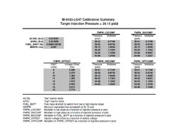
as for kicking up the fuel pressure for more headroom, I always recommend running 55psi of base fuel pressure if you have less than 60lb injectors, note that in my published injector data above it specifies 55psi for injectors below 60s as well, you'll see the published data above for LU47s are correct for 55psi base fuel pressure, simply copy and paste

for reference, when altering the fuel pressure you need to adjust the high slope, low slope, breakpoint, and injector offset, all else stays the same (theoretically)

here's some good info on injector pressure
http://info.efidynotuning.com/inj.htm

can you provide your 90mm flow data from the bench? depending on who you sent it to there is a very very very good possibility that they sent you back a generic curve, I know that sounds screwed up but it happens all the time

here's an actual 90mm flow bench data from nick at pmas, compare this to your data and see what you've got

http://info.efidynotuning.com/maf.htm


SiemensDeka 60

the siemens deka series of injectors are one of the most accurate injectors available, I highly recommend sticking with their posted info and dialing in your fuel by raping the maf curve. I can guarantee you that your actual flow characteristics will not vary that much if any from the published data from siemens.

Everyone recommends the 60 and 80's, but...
This thread was started because My Explorer would not run and pass the HEGO rapid response part of the monitor with the 60's. It used to with old 30lb single pintle injectors, and now still does with the 47's (six hole).

I think some of your post was for 2000streetrod.

Thanks for the confirmation on what to change with increasing fuel pressure.


43.5 psi

At 43.5 psi I have hit about 83-85% duty cycle on the 47lb injectors. That's down from 90% duty cycle, but not far enough.
I have not finished tuning it but it is close.
I will try 55 psi next, keep in mind that with 20lbs of boost my fuel pressure should hit 75 psi.
I have run pressures that high before, when I had the 30lb injectors in.
 

Attachments

  • Untitled1.jpg
    Untitled1.jpg
    59 KB · Views: 132


flexible fuel hose

Since your return type fuel system had a stock fuel pressure range of 30 to 50 psi the flexible hose from the tank to the metal line is probably SAE 30 R6 with a rated working pressure of 50 psi and a burst pressure of 250 psi. I suggest that you replace it with SAE 30 R9 with a rated working pressure of 100 psi and a burst pressure of 900 psi if you haven't already done so.


Fuel Supply

Since your return type fuel system had a stock fuel pressure range of 30 to 50 psi the flexible hose from the tank to the metal line is probably SAE 30 R6 with a rated working pressure of 50 psi and a burst pressure of 250 psi. I suggest that you replace it with SAE 30 R9 with a rated working pressure of 100 psi and a burst pressure of 900 psi if you haven't already done so.

You are killing me!
Now I have to go look at the fuel line to see if there are markings on it.
I have run 55 psi before but the boost wasn't so high back then so max pressure may have been 70 at most.
I guess I was just lucky before if it did not blow out.

Have you had a problem with the stock fuel lines blowing out?
Did you change them over?


split hose

I had a problem with a previous owner replacing the stock flexible hose with a lower grade hose: Fuel leak repair
split.jpg

I think the stock flexible hose was probably heat shrunk onto the fittings. I don't know what the pressure rating of the stock hose is for your 1998.


HEGO Test not running/passing with 43.5 Fuel Pressure

The fuel pressure raised to 43.5
The injector data corrected for the higher fuel pressure
Maf transfer dialed in
Wont run/pass the HEGO rapid response test.
The first picture below is a passed test with the fuel pressure at 39.15
The second picture is a fail with 43.5
The third picture is the same fail with the OBD test state clicked on in LiveLink
 

Attachments

  • zoomed pass.jpg
    zoomed pass.jpg
    69.4 KB · Views: 134
  • zoomed fail.jpg
    zoomed fail.jpg
    67.7 KB · Views: 142
  • zoomed fail OBD on.jpg
    zoomed fail OBD on.jpg
    76.1 KB · Views: 140


Failed

Looking at the two pictures in my last post I would say rate of swing.
Here is the before and after injector data.
 

Attachments

  • 43pt5 injector battery comp.jpg
    43pt5 injector battery comp.jpg
    54.6 KB · Views: 158
  • 39pt15 injector battery comp.jpg
    39pt15 injector battery comp.jpg
    55 KB · Views: 148
  • 43pt5 injector data.jpg
    43pt5 injector data.jpg
    53.7 KB · Views: 146
  • 39pt15 injector data.jpg
    39pt15 injector data.jpg
    53.7 KB · Views: 150


Experiment

I guess I could experiment a little,
I might try putting the tune back to the 39.15 psi 47 lb injector data and leave the fuel pressure at 43.5, rescale the maf and see if that works.

Or leave the 43.5 psi injector data and turn the fuel pressure back to 39.15 and rescale the MAF and see if that works.


injector pulsewidths?

What do the injector pulsewidths look like for pass vs fail? I assume that the injectors are less responsive at increased fuel pressures but at engine speeds of 1750 to 2,000 rpm that shouldn't be a problem. I guess they open faster and close slower as the fuel pressure increases.


Duty Cycle

.037% pass and maf counts 238
.053% fail and maf counts 275

I don't know how to convert Duty cycle to PW


Pw

No clipping or anything on the Pulsewidth.
Now check out Bank 2 on both recordings.
I saw this before, at one time I thought it was a rear O2 sensor.
Now I think the PCM starts to try the high frequency with bank 1, and can not get it to work so never tries to get bank 2 switching that fast.
One of the things that makes me think that is how they look on the good recording, they are completely opposite each other(bank 1 and 2).
This test only has to run and pass for 4 seconds. LOL.
 

Attachments

  • pulse width pass.jpg
    pulse width pass.jpg
    71.6 KB · Views: 118
  • pulse width fail.jpg
    pulse width fail.jpg
    68.4 KB · Views: 130


Cross counting

Here is a shot of right before it entered the test.
I looked at bank 1 and 2 and they both look a little crappy but both are cross counting. This is bank 2 since it doesn't go into the high frequency switching.
Edit: Added Bank 1 (bottom picture).
 

Attachments

  • before and during test.jpg
    before and during test.jpg
    72.5 KB · Views: 125
  • B1 before and during test.jpg
    B1 before and during test.jpg
    75.1 KB · Views: 147


Join the Elite Explorers for $20 each year.
Elite Explorer members see no advertisements, no banner ads, no double underlined links,.
Add an avatar, upload photo attachments, and more!
.


MTF changes?

The deviation of the O2 sensors appears to be reduced when going from 39.15 to 43.5 psi. In my tune the deviation is dependent upon load and RPM. I don't recall you mentioning altering the MTF for the higher pressure tune so the load calculations wouldn't change. However, the response of the fuel injectors probably decreased. I suggest increasing the "authority" of the PCM to achieve the limit of the O2 sensors. This should increase the deviation and slope of the deviation resulting in faster switching. You might try increasing the values in the table by 20%.
PkToPkO2Amp.jpg

If that doesn't result in O2 sensor voltage clipping then increase the values again. This may also be the solution for getting the Deka 60s to pass the test.


Back
Top