Desert_AIP
Active Member
- Joined
- January 25, 2017
- Messages
- 97
- Reaction score
- 53
- Year, Model & Trim Level
- 1998 Explorer XLT 4WD
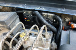
I installed a relay box to control my external lights and winch power.
There aren't any ready made products for this, and as I looked at piecing together a positive and negative terminal header, fuse block, relays and terminal blocks for the switches and outputs it was looking very complicated.
Under hood real estate is also a challenge.
I finally grabbed a Chinese copy of the SPOD system for Jeep Wranglers.
I only wanted the relay box itself and switch umbilical so I didn't want to fork out several hundred dollars for the real SPOD system.
I paid $99, I didn't use the switch panel piece at all.
The box has six 40A relays, an 80A input breaker to the positive header, and individual fuses for each relay output.
The first three relays are for controlling the three forward off road lights.
The fourth relay is to switch ground to those forward lights, and is enabled by the high beam headlights. So they won't come on if the high beams aren't on, and if I have to dim for an oncoming car, they all dim with the headlights without turning off the lighting switches themselves.
The fifth relay is for some lights on my roof rack I use for ditch and camp lights.
The sixth relay controls power to my winch. (I originally switched the control ground to the winch, that's the wiring you can see in the pics, but the control was still finding a ground somehow, so I changed it to switch the control hot instead and now it works correctly).
The three forward lights and the winch use a key switched hot as their inputs, So they will all go off when the key is removed.
The high beam switch uses the high beam hot as described above.
The side lights (roof rack) uses a constant hot. There are local switches near the roof rack lights themselves. This way I can leave this master switch on, and use the rack lights as camp lights by switching them on and off locally and externally (so I don't have to open the door, or have the key in to activate them). The master switch allows me to deactivate that function.
I pulled these signals from two unused fuse locations and the high beams fuse with fuse taps in the fuse panel inside.
To wire the negative switching, I pulled the fuse off the fourth relay. The input side of the fuse is connected to the main hot header input, the output side of the fuse is connected to the input terminal of the relay. I capped the hot side of the fuse terminal with a connector, then I ran two 12 AWG wires from the ground bus to the input side of the relay (the jumpers in the photo). When that relay is activated by the high beams on, the ground is routed tot eh output terminal of the relay. So the three forward lights are wired to their respective relay hot outputs with fuses, and all three grounds are routed to this ground output (which is why I used two 12AWGs because it has to carry the total of all three lights (about 425W ~35A). The relays are rated for 40A.
I made up some harnesses using Deutsch connectors for the lights, and made up pigtails that come out of the relay box since where I mounted it I don't have ready access to make connections.
I modified the relay box by cutting off the legs of the original mounting bracket and installing two 6mm stainless bolts as studs for mounting.
I also opened up the wiring access hole to feed it with 4AWG wire instead of the supplied 8 AWG. I replaced the original circuit breaker with a better model that had covered contacts.
I mounted the relay box along the driver's side fender outboard of the battery. I drilled two holes in the fender/hood mounting seam and passed the studs on the box up through them and secured with two lock nuts. The negative bus bale attaches to the ground screw behind the left headlight.
Then it was a simple matter to route the harnesses to the lights and plug them in.
I did have to cut the switch umbilical to pass the cable through the firewall, so I reconnected it using an 8 pin Deutsch connector under the hood.
I could have just soldered and heat shrinked it back together, this seemed cleaner.
Attachments
-
 Relay 01.jpg49 KB · Views: 64
 -
 Relay 02.jpg90 KB · Views: 73
 -
 Relay 03.JPG70.9 KB · Views: 75
 -
 Relay 04.JPG144.3 KB · Views: 68
 -
 Relay 05.JPG199.5 KB · Views: 65
 -
 Relay 06.JPG120.4 KB · Views: 63
 -
 Relay 07.JPG148.1 KB · Views: 72
 -
 Relay 08.JPG157.7 KB · Views: 76
 -
 Relay 09.JPG195.5 KB · Views: 99
 -
 Relay 10.JPG170 KB · Views: 69
 -
 Relay 11.JPG155.8 KB · Views: 68
 -
 Relay 12.jpg155.9 KB · Views: 75


